
Print head apparatus with malfunction detector

a technology of malfunction detector and print head, which is applied in the direction of printing and other printing apparatuses, etc., can solve the problems of head running out, too late for appropriate correction, and the nozzle of the print head may be blocked

Inactive Publication Date: 2007-07-31
HEWLETT PACKARD DEV CO LP
View PDF22 Cites 11 Cited by
  • Summary
  • Abstract
  • Description
  • Claims
  • Application Information

AI Technical Summary

Benefits of technology

[0004]Accordingly, it is an object of the present invention to provide a print head that can detect a malfunction therein.
[0005]It is another object of the present invention to provide a print head that can detect such conditions as a clogged nozzle, no fire and dry fire.

Problems solved by technology

Problems associated with current printers and print head arrangements include that the print head may run out of ink while printing, the print head nozzle may become clogged and the ink expulsion mechanism may not fire, amongst other malfunctions.
At this point it is too late for appropriate correction.
These techniques, however, are limited in scope and do not, for example, detect when a nozzle is clogged or unclogged.

Method used


Image

  • Print head apparatus with malfunction detector
  • Print head apparatus with malfunction detector
  • Print head apparatus with malfunction detector

Examples


Embodiment Construction

taken together with the drawings.

BRIEF DESCRIPTION OF THE DRAWINGS

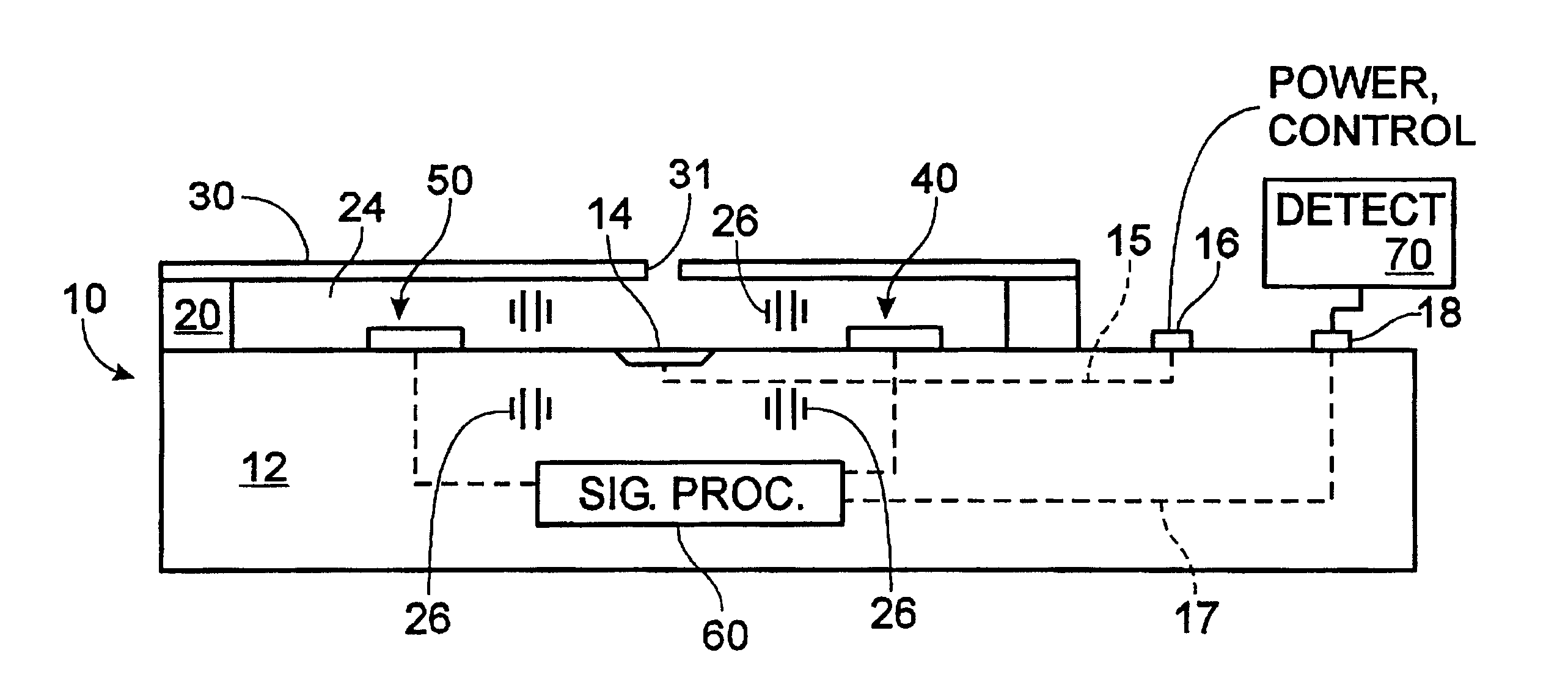
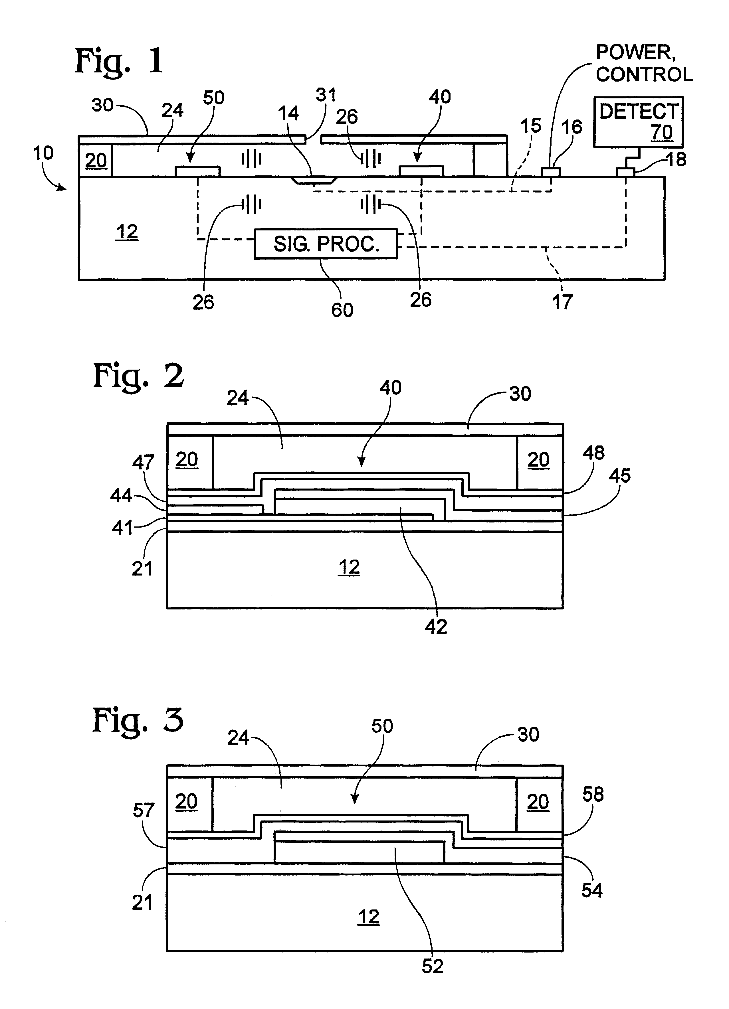
[0010]FIG. 1 is a cross sectional side view of a print head in accordance with the present invention.

[0011]FIG. 2 is a side view of a piezoelectric acoustic wave transducer in accordance with the present invention.

[0012]FIG. 3 is a side view of a portion of an interdigitated pressure wave transducer in accordance with the present invention.

[0013]FIG. 4 is a plan view of an arrangement of piezoelectric acoustic pressure wave transducers and interdigitated piezoelectric pressure wave transducers in a print head in accordance with the present invention.

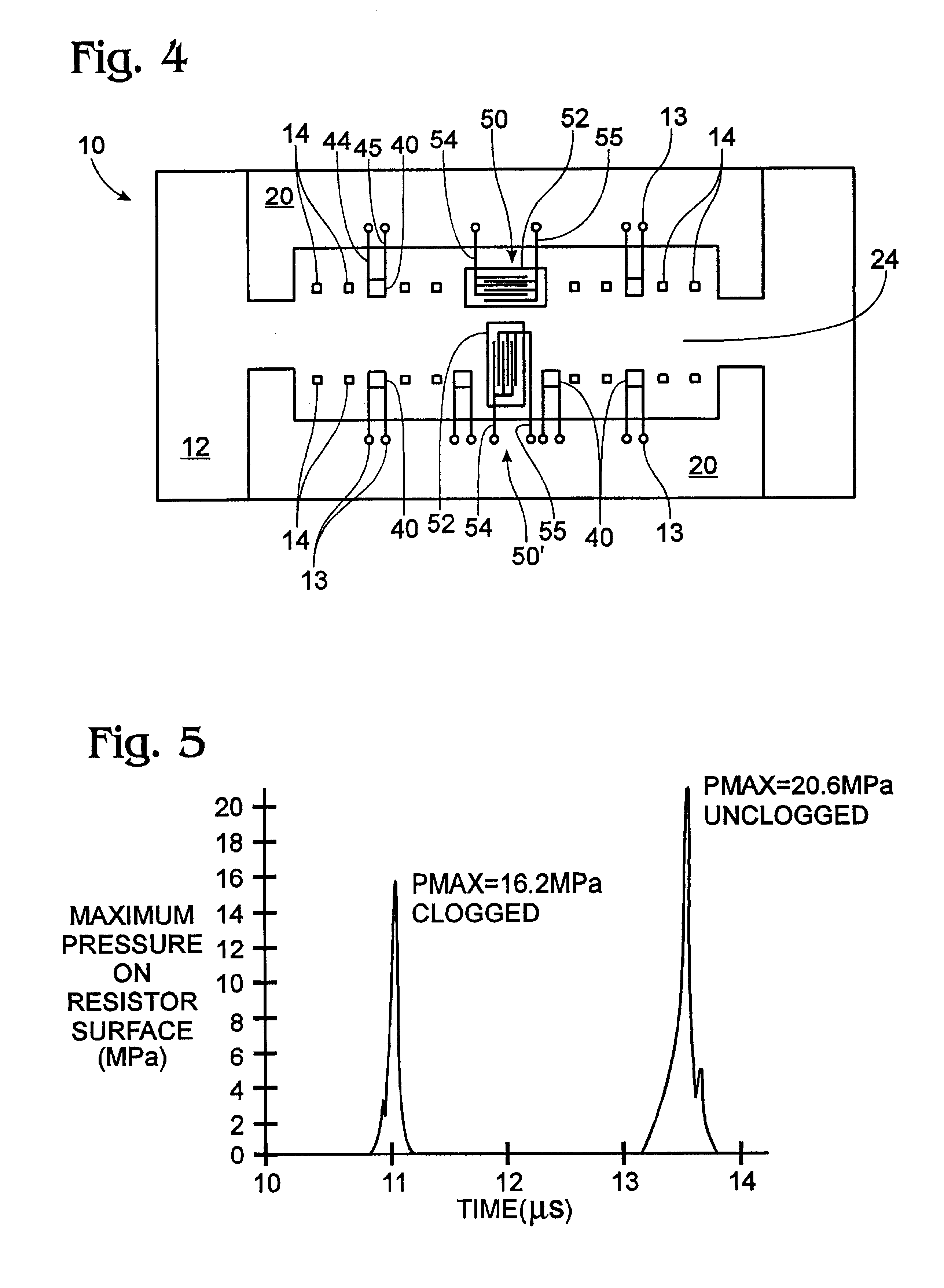
[0014]FIG. 5 is a graph illustrating the pressure on an expulsion mechanism surface versus time for a clogged nozzle firing and an unclogged nozzle firing.

DETAILED DESCRIPTION

[0015]Referring to FIG. 1, a cross sectional side view of a print head 10 in accordance with the present invention is shown. Print head 10 includes a substrate in or on which is provided an ink expuls...


PUM


Abstract

A print head and method that are capable of detecting a plurality of performance conditions such as a dry-fire, no-fire or clogged-nozzle condition. Pressure wave sensors within a print head are disclosed that are capable of detecting pressure waves generated by the firing of an ink expulsion mechanism. The characteristics of the pressure wave generated by the firing event (e.g., magnitude and timing) are indicative of the operating condition within the head. Multiple sensor types are disclosed.

Description

FIELD OF THE INVENTION[0001]The present invention relates to print heads used in printers and plotters and the like and, more specifically, to detecting malfunctions within such print heads.BACKGROUND OF THE INVENTION[0002]Printers and plotters are known in the art and include those made by Hewlett-Packard, Canon and Epson, amongst others. In the discussion that follows, printers and plotters are referred to collectively with the term “printers”. Problems associated with current printers and print head arrangements include that the print head may run out of ink while printing, the print head nozzle may become clogged and the ink expulsion mechanism may not fire, amongst other malfunctions. Evidence of such malfunctions are usually detected when the printed document is pulled out of the printer and examined visually. At this point it is too late for appropriate correction. Some types of electronic sensing are known in the art, such as techniques for detecting when an ink expulsion me...

Claims


Application Information

Patent Timeline
Patent Type & Authority Patents(United States)
IPC IPC(8): B41J29/393B41J2/01B41J2/125B41J2/05
CPCB41J2/0451B41J2/0458B41J2/14072B41J2/14153
Inventor PAASCH, ROBERT
Owner HEWLETT PACKARD DEV CO LP
Learn More