
Method of detecting resonant frequency, method of selecting resonance frequency, and device for detecting resonant frequency sensor

a technology of resonant frequency and resonant frequency sensor, which is applied in the direction of instruments, heat measurement, specific gravity measurement, etc., can solve the problems of inaccuracy of detecting resonant frequency depending on skill or experience, and difficulty in listening to music or voice from speaker. to achieve accurate detecting of resonant frequency

Inactive Publication Date: 2007-07-31
TOA CORP
View PDF13 Cites 10 Cited by
  • Summary
  • Abstract
  • Description
  • Claims
  • Application Information

AI Technical Summary

Benefits of technology

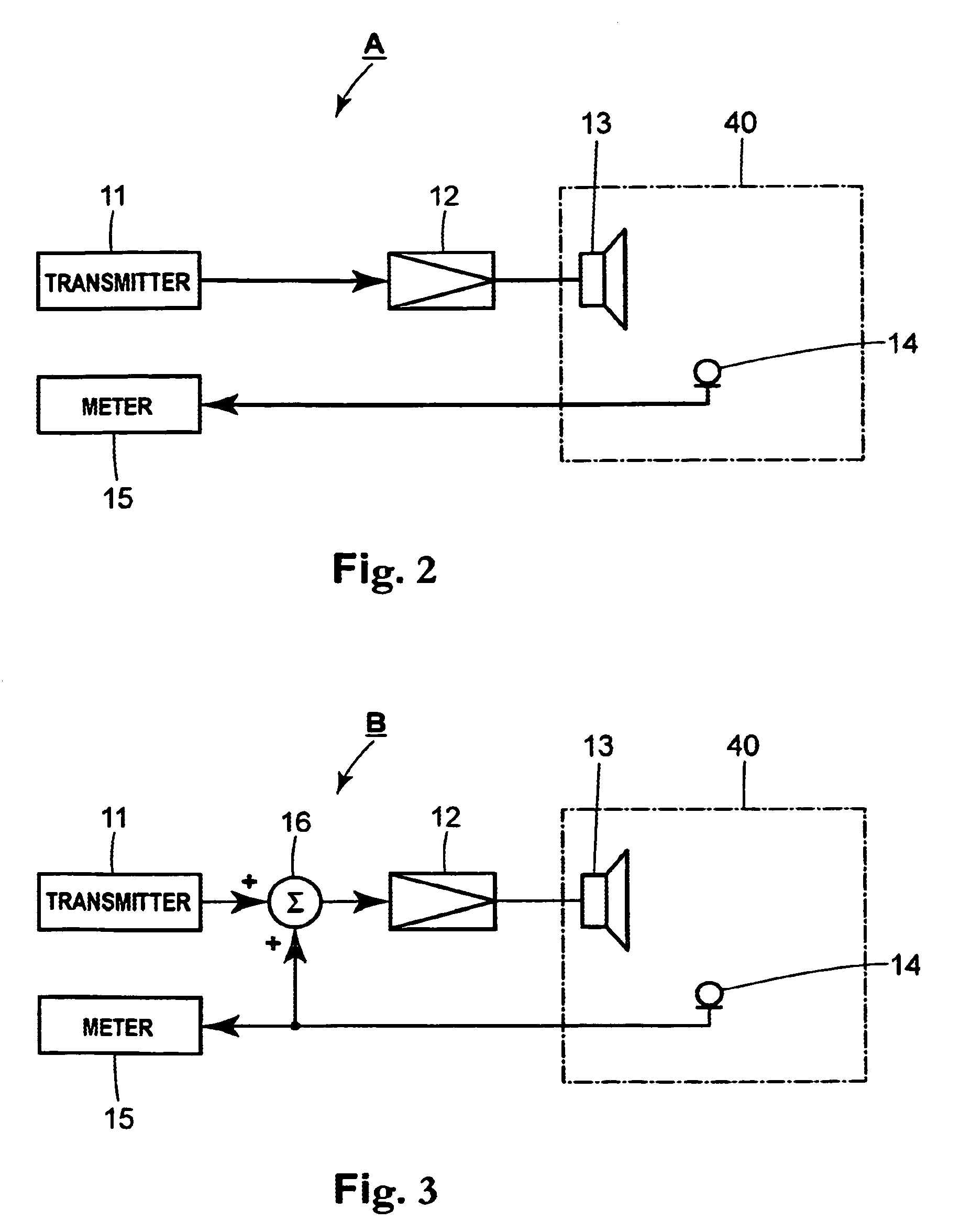
The present invention provides a method and device for accurately detecting the resonant frequency of a resonant space without needing any experience or skill. The method involves measuring the amplitude frequency characteristic of a loud sound wave generated by a speaker and received by a microphone in the resonant space. The device includes a sound source, a signal synthesization switching means, and a measuring means for measuring the amplitude frequency characteristic. The resonant frequency can be detected based on a difference between the first and second amplitude frequency characteristics, which shows the effect of the resonant characteristic of the resonant space. The invention also provides a method for objectively selecting the dip center frequencies to be set in a dip filter in decreasing order of amplitude levels in the second amplitude frequency characteristic. This helps to prevent resonance in the loud sound space.

Problems solved by technology

For example, when acoustic equipment such as a speaker is installed in a hall or a gymnasium to radiate a loud sound wave from a speaker, music or voice from the speaker is sometimes difficult to listen to because of the presence of a resonant frequency in this space (loud sound space in which the acoustic equipment is installed).
. . .” The resonant sound is not a sound wave to be radiated from the speaker and makes it difficult to listen to the music or the voice from the speaker.
Such detection of the resonant frequency depending on the skill or experience is not always accurate.
Further, this has impeded automatic measurement and automatic adjustment of the acoustic equipment installed in the loud sound space or the like.

Method used


Image

  • Method of detecting resonant frequency, method of selecting resonance frequency, and device for detecting resonant frequency sensor
  • Method of detecting resonant frequency, method of selecting resonance frequency, and device for detecting resonant frequency sensor
  • Method of detecting resonant frequency, method of selecting resonance frequency, and device for detecting resonant frequency sensor

Examples


Embodiment Construction

[0024]Embodiments of the present invention will be described with reference to the drawings.

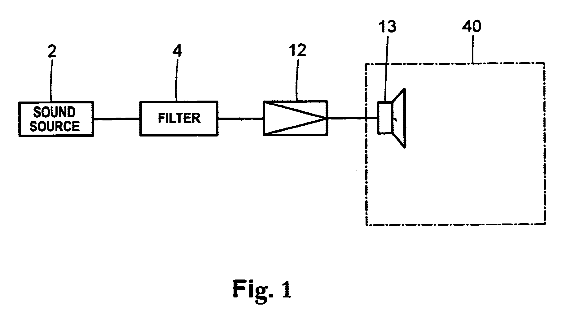
[0025]FIG. 1 is a schematic view of a construction of an acoustic system installed in a loud sound space (e.g., concert hall or gymnasium) 40. The acoustic system comprises a sound source device 2, a dip filter 4, an amplifier 12, and a speaker 13. The sound source device 2 may be a music instrument such as a CD player for playback of, for example, music CD, or a microphone. While the sound source device 2 is illustrated as being located outside the loud sound space 40 in FIG. 1, it may alternatively be located within the loud sound space 40. The sound source device 2 may be, for example, a microphone installed within the loud sound space 40. The dip filter 4 serves to remove a signal component in a specified frequency from a signal output from the sound source device 2 and to output the resulting signal to the amplifier 12. The amplifier 12 amplifies the signal output from the dip filter 4 a...


PUM


Abstract

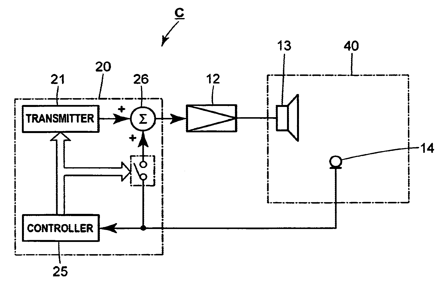
A device for detecting a resonant frequency comprises a sound source, a switch, a mixer, and a sound meter. The switch and mixer are capable of switching between a first state in which the switch and mixer output a measurement signal and a second state in which the switch and mixer output a synthesized signal containing the measurement signal and the signal output from a microphone. The device detects the resonant frequency based on comparison between the first amplitude frequency characteristic measured in the first state and the second amplitude frequency characteristic measured in the second state.

Description

[0001]The present application claims the benefit of priority of International Patent Application No. PCT / JP2003 / 015703 filed on Dec. 9, 2003, which application claims priority of Japanese Patent Application No. 2003-021558 filed Jan. 30, 2003 and Japanese Patent Application No. 2002-357124 filed Dec. 9, 2002. The entire text of the priority application is incorporated herein by reference in its entirety.TECHNICAL FIELD[0002]The present invention relates to a method and device for detecting a resonant frequency in a resonant space, and a method of selecting a resonant frequency to be set as a dip center frequency in a dip filter from detected resonant frequencies.BACKGROUND ART[0003]In some cases, it is necessary to detect a resonant frequency in a resonant space. For example, when acoustic equipment such as a speaker is installed in a hall or a gymnasium to radiate a loud sound wave from a speaker, music or voice from the speaker is sometimes difficult to listen to because of the pr...

Claims


Application Information

Patent Timeline
Patent Type & Authority Patents(United States)
IPC IPC(8): G01H7/00H04R29/00G01H13/00G01H17/00G01R27/28G01R23/165G10K15/00H04R3/00H04R3/02
CPCG01H13/00H04R3/002H04R3/02
Inventor HIGASHIHARA, DAISUKE
Owner TOA CORP
Learn More