Multiaperture sample positioning and analysis system
a multi-aperture, sampling technology, applied in the direction of liquid/fluent solid measurement, biomass after-treatment, enzymology, etc., can solve the problems of preventing patch-clamp technology, requiring a tremendous effort in technical installation and highly qualified operators, and reagents that are typically not sensitive enough for single cell measuremen
- Summary
- Abstract
- Description
- Claims
- Application Information
AI Technical Summary
Benefits of technology
Problems solved by technology
Method used
Image

Examples
example 1
Substrate Chip
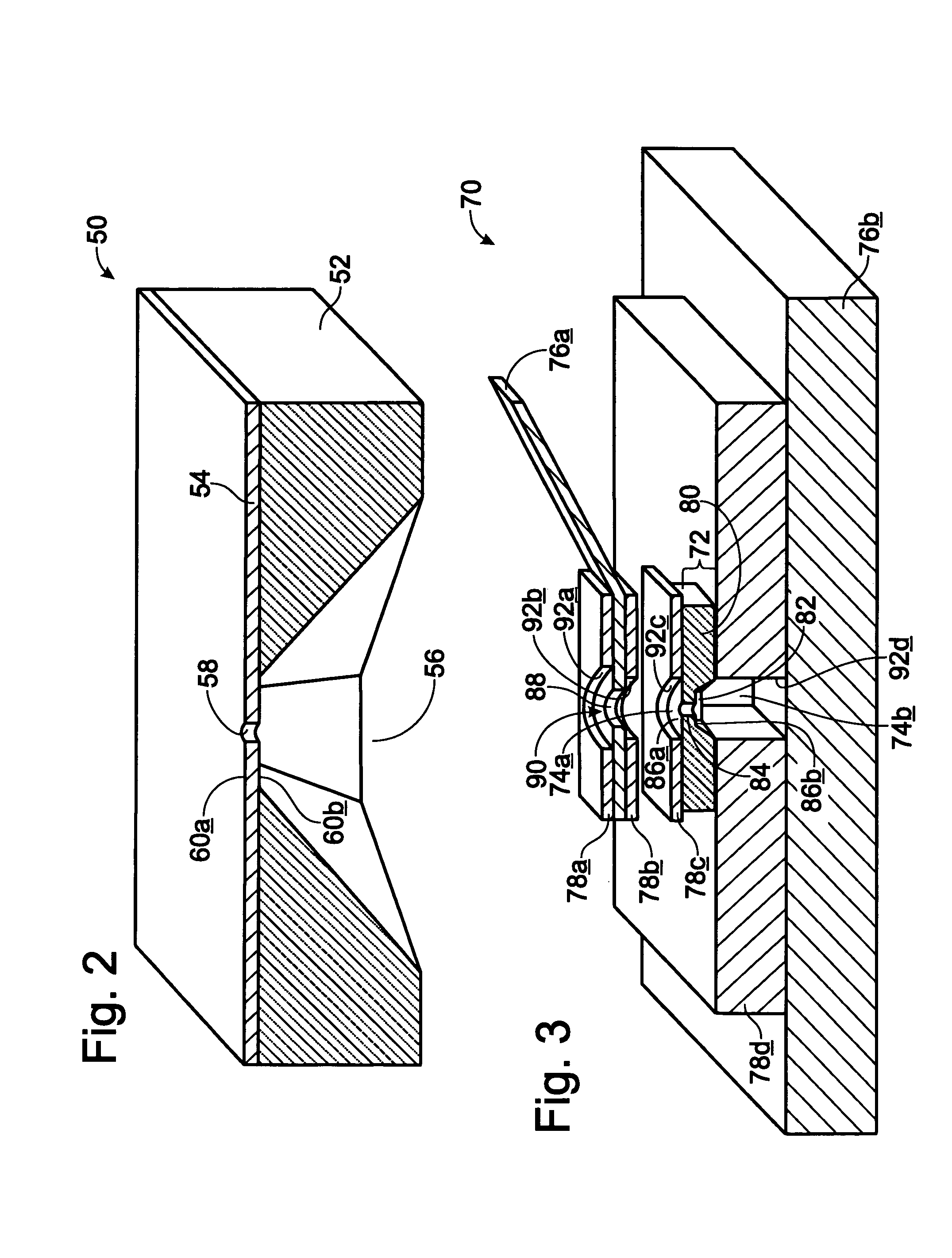
[0113]This example, illustrated in FIG. 2, describes an exemplary Si / SiO2 chip substrate 50 for use in positioning and / or studying cells, vesicles, and the like, in accordance with aspects of the invention.
[0114]The substrate includes a body 52, a surface layer 54, a window 56, and an aperture 58. The body comprises an at least substantially planar, commercially available silicon wafer. The surface layer comprises a silicon oxide or silicon oxynitride layer formed adjacent one or more sides of the body. In this embodiment, the surface layer has a thickness of at least about 50 to 200 nm and provides at least one adhesion surface 60a,b capable of binding cells, vesicles, and / or other samples. The window and aperture comprise openings through the body and surface layer, respectively. These openings are at least substantially concentrically aligned, with dimensions sufficient to allow fluid contact between opposite sides of the substrate.
[0115]The substrate may be produce...
example 2
Measurement System with Planar Electrodes
[0117]This example, illustrated in FIG. 3, describes an exemplary measurement system 70 having planar electrodes, in accordance with aspects of the invention.
[0118]The measurement system includes a substrate 72, at least two fluid compartments 74a,b, at least two redox electrodes 76a,b, and optionally at least four spacers 78a-d. In this embodiment, all of these components are at least substantially planar; however, in other embodiments, one or more of these components may have a different geometry. Generally, samples may be introduced into either compartment, and measurements may be performed with the system in any orientation. However, to simplify the description, the top fluid compartment 74a and top electrode 76a (as drawn) are referred to here as the measurement compartment and measurement electrode, and the bottom fluid compartment 74b and the bottom electrode 76a (as drawn) are referred to as the reference compartment and the reference...
example 3
Measurement System with Point or Wire Electrodes
[0124]This example, illustrated in FIG. 4, describes an exemplary measurement system 110 having point or wire electrodes, in accordance with aspects of the invention.
[0125]The measurement system includes a substrate 112, two fluid compartments 114a,b and two point or wire electrodes 116a,b. The substrate and fluid compartments are used to support samples and fluids, respectively, as described above. The substrate includes a body 118, a window 120, and an aperture 122 connecting the two fluid compartments. The substrate further may be surface modified and / or fastened to a holder, including a glass or Teflon holder. The electrodes are used to apply an electric potential and associated electric field across the aperture, also as described above. Here, the electrodes comprise the chlorinated end surfaces 124a,b of two silver wires 126a,b, or, alternatively, two silver electrodes, disposed above and below the substrate. The electrodes prefe...
PUM
| Property | Measurement | Unit |
|---|---|---|
| diameter | aaaaa | aaaaa |
| diameter | aaaaa | aaaaa |
| diameter | aaaaa | aaaaa |
Abstract
Description
Claims
Application Information
 - R&D
- Intellectual Property
- Life Sciences
- Materials
- Tech Scout
- Unparalleled Data Quality
- Higher Quality Content
- 60% Fewer Hallucinations
Browse by: Latest US Patents, China's latest patents, Technical Efficacy Thesaurus, Application Domain, Technology Topic, Popular Technical Reports.
© 2025 PatSnap. All rights reserved.Legal|Privacy policy|Modern Slavery Act Transparency Statement|Sitemap|About US| Contact US: help@patsnap.com