
High-lift, low drag fin for surfboard and other watercraft

a technology for surfboards and watercraft, applied in the direction of special-purpose vessels, vessel construction, hull parts, etc., can solve the problems of excessively large increased drag, excessive surface area of endplates, etc., to reduce the induced drag of tip-vortex, minimize stalling, and minimize stalling

Active Publication Date: 2007-07-17
WAVEGRINDER
View PDF11 Cites 18 Cited by
  • Summary
  • Abstract
  • Description
  • Claims
  • Application Information

AI Technical Summary

Benefits of technology

"The invention is a surfboard or watercraft fin designed to increase lift and decrease drag, which improves maneuverability and allows surfers to surf for longer periods of time without exhaustion. The fin has a symmetrical, rounded-nose foil section that maximizes lift at a wide range of angles of attack while minimizing drag. It also has a forward-projecting fin root section that reduces interference drag and a cutaway at the trailing edge to avoid tip-vortex drag. The fin can be used as a side fin with winglets that reduce drag and promote turning. Overall, the fin design improves the efficiency and performance of surboards and watercraft."

Problems solved by technology

But of the use of planar winglets, as opposed to endplates, fences, or wings to increase lift while decreasing drag by reducing tip-vortex generation has not been observed in prior art.
The surface area of the endplates was excessively large and increased drag as contrasted with the current disclosure, and were not designed so as to assist turning.
The surface area of the endplate was excessively large and increased drag as contrasted with the current disclosure.
Both systems require vast quantities of power to make the system work, and have drag that would preclude their use in surfing because of the drag and thus the resistance to paddling and wave catching, as contrasted with the current disclosure.
U.S. Pat. No. 4,320,546 does not disclose a foil section designed to promote laminar flow over a wide range of yaw angles, and thus will not function to promote turning over a wide range of yaw angles, as does the current disclosure.
The lift from one side of the tube thus cancels the lift on its opposite side, producing drag.

Method used


Image

  • High-lift, low drag fin for surfboard and other watercraft
  • High-lift, low drag fin for surfboard and other watercraft
  • High-lift, low drag fin for surfboard and other watercraft

Examples


first embodiment

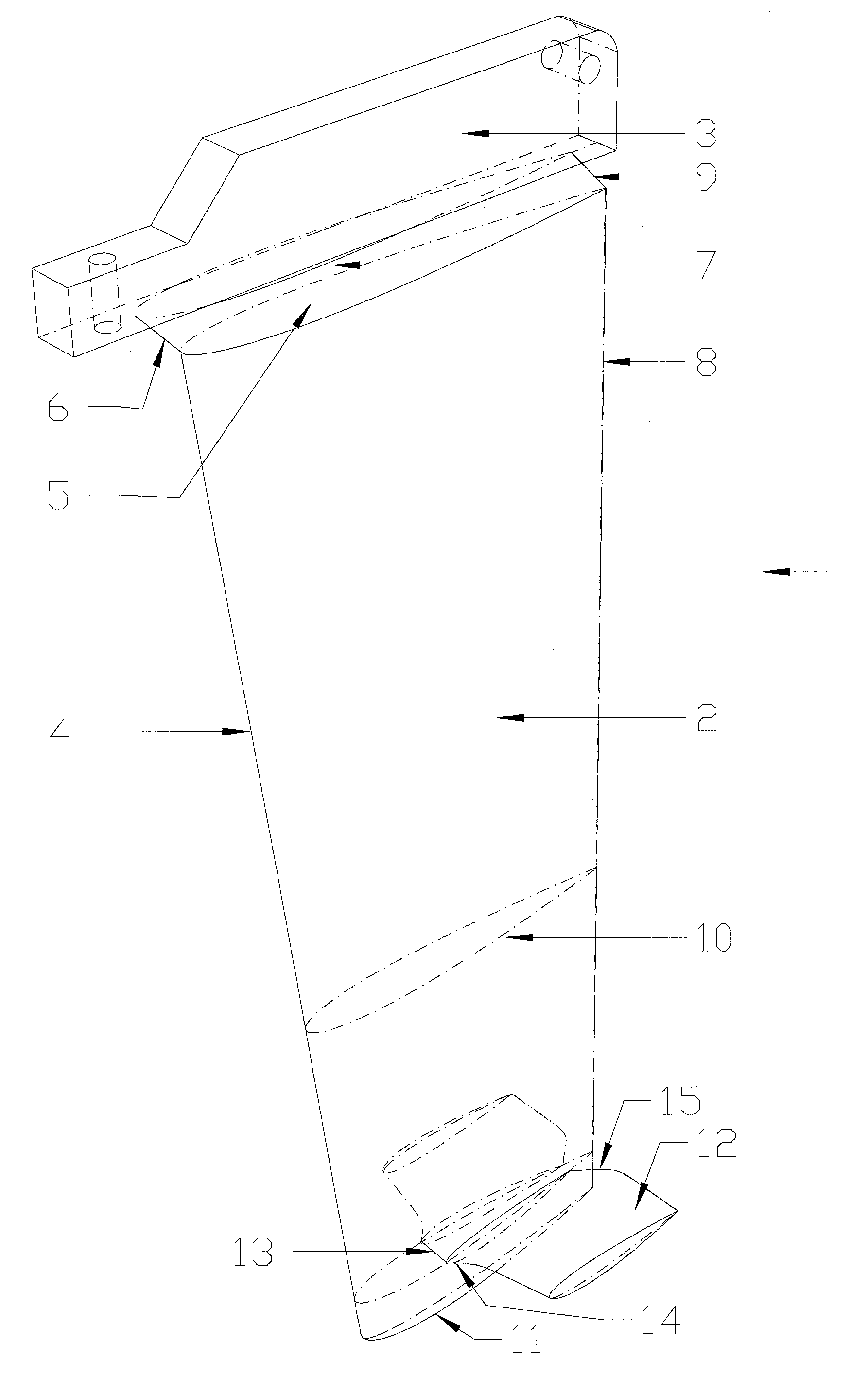
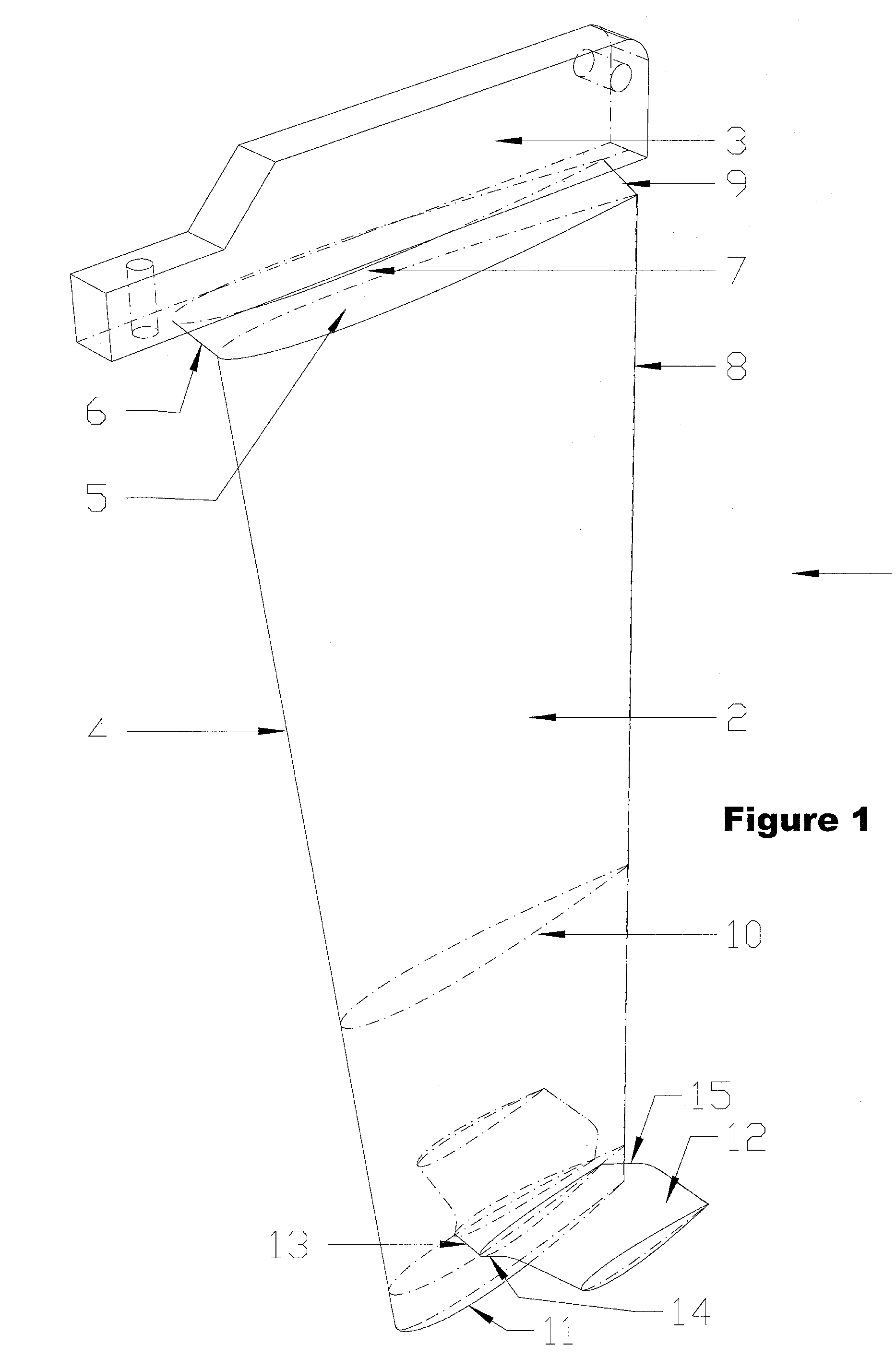
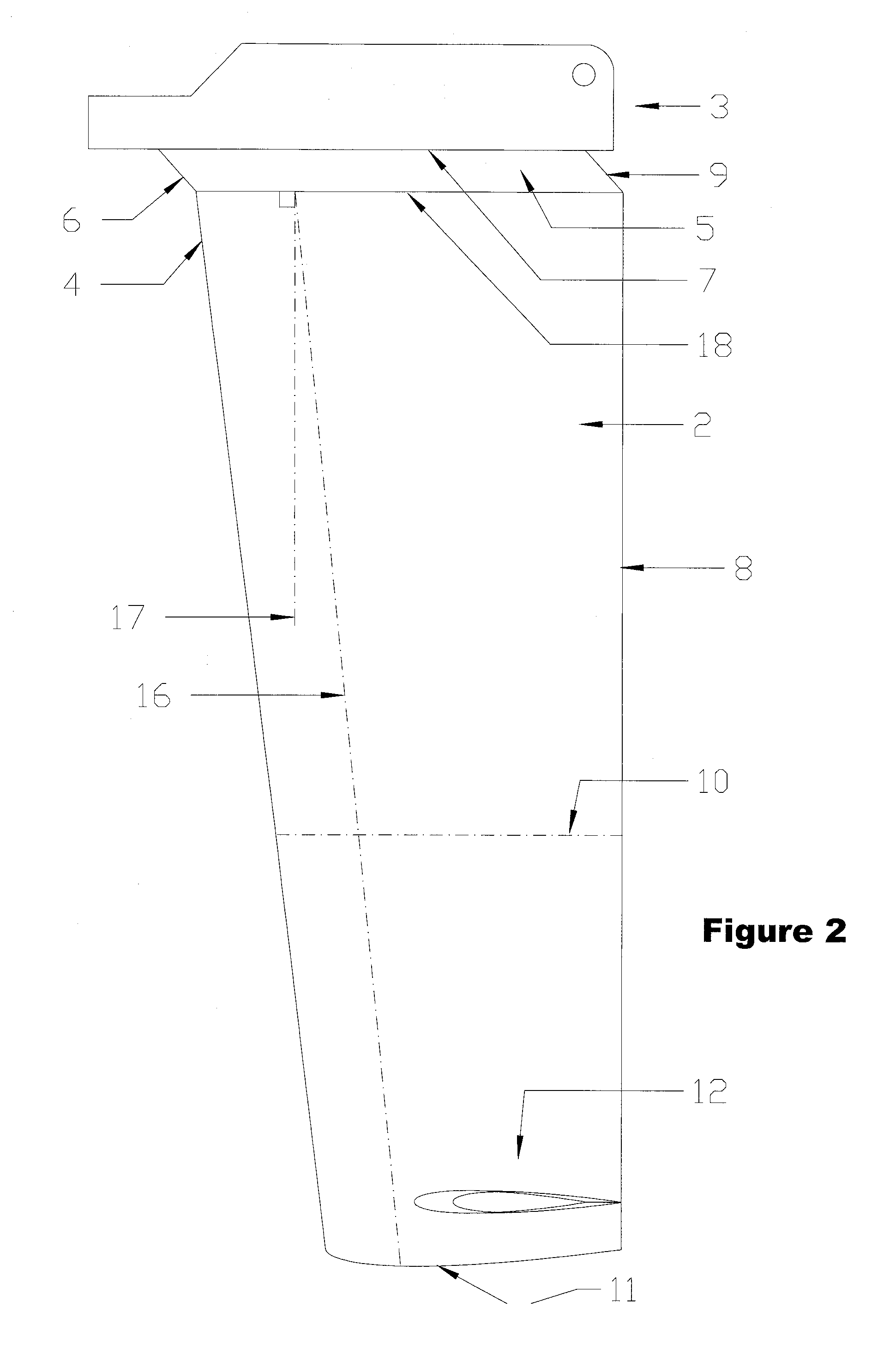
[0073]Referring now to the drawings and the characters of reference marked thereon, FIGS. 1 through 4 illustrate the present invention. FIG. 1 is a perspective view of the invention 1, exhibiting a high-aspect-ratio planform 2 of 3:1 in this embodiment, which is connected to the fin base 3. The fin base 3 is designed to fit the fin 1 into common fin boxes available on the market and commonly used in surfboards and other watercraft.

[0074]Between the high-aspect-ratio planform 2 and the fin base 3 is a forwardly displaced section of the fin 5, which forward-shifted displacement creates both a forwardly upwardly sloped projection 6 between the leading edge 4 of the fin planform 2 and the fin root 7 and, at the upper end of the fin's trailing edge 8, a cutaway 9. Although cutaways have been employed alone in some designs available, the invention combines the trailing-edge cutaway feature and the forwardly projecting root leading edge to minimize interference drag, the drag caused by the...

second embodiment

[0086]FIG. 8 is a front view of the invention in the second embodiment as a side fin 20 with a single planar winglet 22.

[0087]FIG. 9 shows a third embodiment 24 of the invention, this third embodiment with longer-spanned planar winglets 25 placed directly at the fin tip 11, and with another pair of winglets 26 placed at mid-fin span. Such horizontally arranged, larger planform, mid-span winglets increase lift in the vertical direction, reduce mid-span fin downwash, but increase drag to some extent. But the greater horizontal surface area and thus the greater vertical lift and vertical stability of this embodiment give the surfer or watercraft rider a greater horizontal lifting surface, which despite the penalty in drag, assists riders' movement forward on a surfboard from the take-off stance depicted in FIG. 10 to a point forward on the board such as in noseriding, as shown in FIG. 11. As a rider moves from the rear of the board toward the front, the tail of the board tends to lift ...

third embodiment

[0088]Still referring to FIG. 9, the winglet placement directly at the fin tip 11 has an important safety benefit. Typical surfboard fins that have a high taper ratio get very thin at the tip, and can cause injuries similar to a blunt spear when the board is thrown onto the surfer or vice versa. Waves pounding against the board can drive the tail into the surfer causing fin injuries, and surfers can be thrown by waves onto the upraised fins of overturned boards, directly onto the fin, casing injuries. The placement of the winglets at the fin tip, on the other hand, protects the surfer somewhat from such injuries. Although the winglets themselves are smaller than typical fin tips, the winglets are arranged in the same plane as the surfboard, mitigating the force with which a wave can throw the board onto the surfer, and the force with which the surfer can strike the board, because the board on edge presents less surface to the coming wave, or when fallen upon while on edge, sinks and...


PUM


Abstract

This invention discloses a fin, for use on a surfboard and other watercraft, of a low-drag, high-lift, high-aspect-ratio, low-sweepback-angle planform of symmetrical foil section, with a fit root section that has a forwardly projecting leading edge and cutaway at the trailing edge, alone or in combination with winglets placed on the vertical fin element so as to minimize tip-vortex drag, so as to make the surfboard or watercraft more maneuverable, easier to propel through the water, and to stabilize the surfboard or watercraft.

Description

FIELD OF THE INVENTION[0001]The present invention relates to stabilizing fins for watercraft such as surfboards and other watercraft, and more particularly to a fin that not only stabilizes the surfboard or watercraft laterally and vertically, but also assists maneuverability and turning of the surfboard or watercraft.BACKGROUND OF THE INVENTION[0002]Aerodynamics and hydrodynamics have much in common because both disciplines involve the study of the movement of a fluid, air or water, past a structure. Surfing, and other water sports such as sailing, power boating, windsurfing, kite surfing, wakeboarding and water skiing, for example, thus share some common aspects derived not only from aerodynamic principles, but also from hydrodynamic principles. This disclosure relates to an invention intended primarily for use on surfboards, but given the teachings of this disclosure is easily practiced in or adaptable to sports involving other watercraft such as those mentioned.[0003]The sport o...

Claims


Application Information

Patent Timeline
Patent Type & Authority Patents(United States)
IPC IPC(8): B63B3/38
CPCB63B35/7926B63B32/60B63B32/66
Inventor SIMPSON, DOUGLAS JAMES
Owner WAVEGRINDER
Learn More