
Welding accessory arrangement

a welding accessory and accessory technology, applied in the field of welding accessory arrangement, can solve the problems of difficulty in finding a suitable location for all the accessories used with the welder, difficulty in assembling the welder, and difficulty in finding a suitable location, etc., to achieve convenient connection of welding accessories, easy assembly, and convenient transportation

Inactive Publication Date: 2007-07-10
LINCOLN GLOBAL INC
View PDF20 Cites 43 Cited by
  • Summary
  • Abstract
  • Description
  • Claims
  • Application Information

AI Technical Summary

Benefits of technology

The integrated design reduces the burden of setup and transport, minimizes damage to equipment, and ensures organized storage and access to welding accessories, enhancing operational efficiency and convenience.

Problems solved by technology

As a result, the initial set up of a welder in a particular location and / or the movement of the welder to various locations is both difficult and time consuming.
In addition, there sometimes is difficulty finding a suitable location for all the accessories used with the welder.
As a result, it is sometimes difficult to find a suitable location to position the welder and the various accessories about the welder so that a welding operation can proceed.
Bunching up the welding cable can result in damage to the fluid tubes and / or electrical connections inside the cable.
In addition, laying the welding gun or torch on the ground and / or placing the welding gun or torch on the top of a welder can result in damage to the welding gun or torch if the welding gun or torch is inadvertently stepped on and / or falls off the top of the welder.
During the transport of the welder to various locations, the welding cable typically must be disconnected from the welder and separately transported, since there is no convenient manner of transporting the welding gun or torch and welding cable with the welder without exposing the welding cable and welding gun or torch to damage.

Method used


Image

  • Welding accessory arrangement
  • Welding accessory arrangement
  • Welding accessory arrangement

Examples


Embodiment Construction

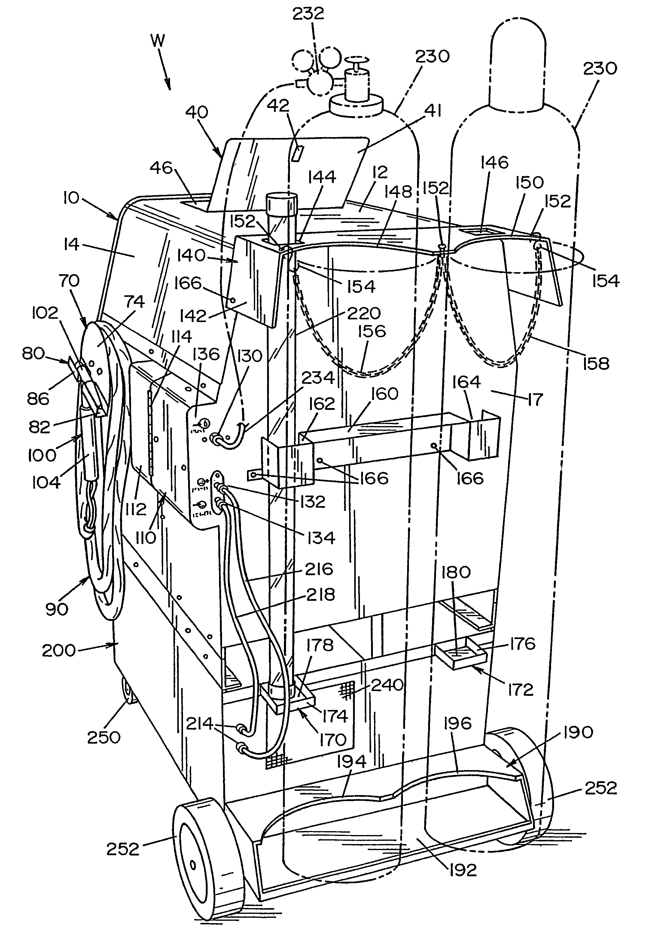
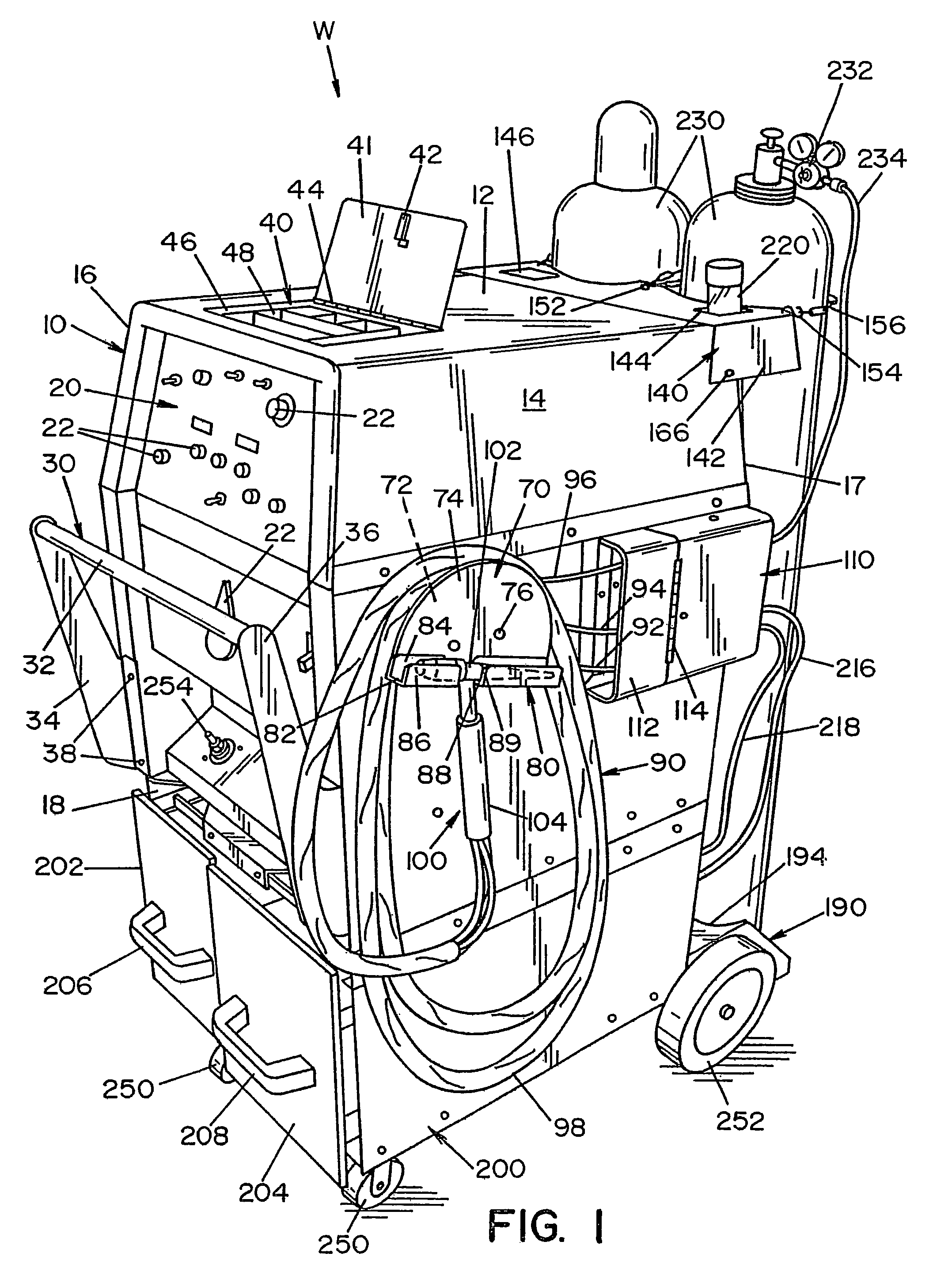
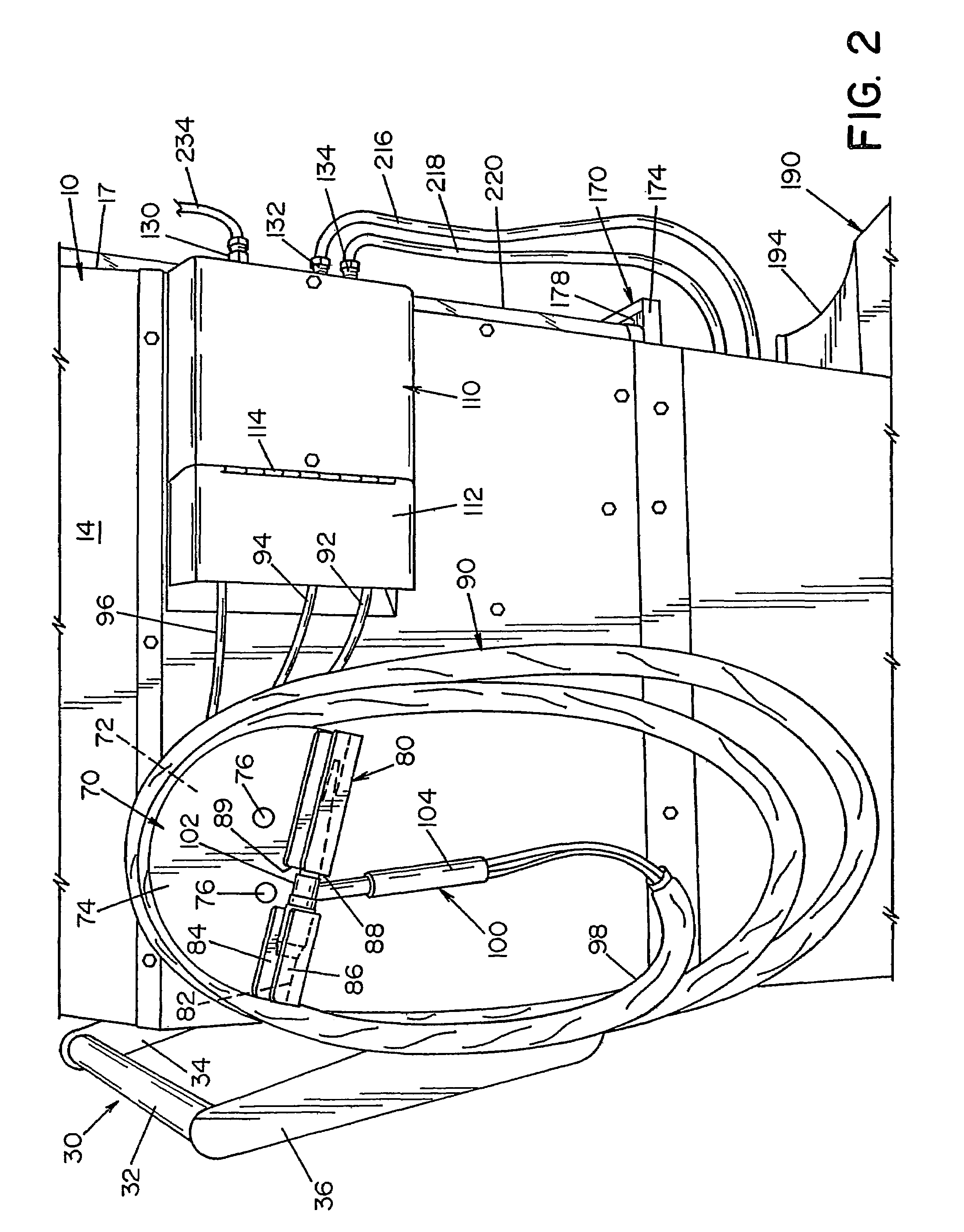
[0034]Referring now to the drawings wherein the showings are for the purpose of illustrating the preferred embodiments of the invention only and not for the purpose of limiting the same, FIGS. 1-6 illustrate a welder W which includes several welding accessories connected to welder housing 10. As shown in FIG. 1, welder housing 10 includes a top 12, two sides 14 and 16, a back 17, and a base 18. On the face of the welder housing is a control panel 20 which includes several control switches 22. These control switches control the parameters of the welder for a particular welding process. A push bar 30 is connected to the front of the welder housing to enable an operator to conveniently move the welder housing to various locations. The push bar 30 includes a handle 32 that is connected between the ends of two arms 34, 36. The arms are bolted to the welder housing by arm bolts 38.

[0035]Referring now to FIGS. 1 and 6, the top of welder housing 10 includes a tool holder 40. Tool holder 40 ...


PUM

PropertyMeasurementUnit
currentaaaaaaaaaa
timeaaaaaaaaaa
voltageaaaaaaaaaa

Abstract

A welding accessory system for a welder that includes a welder having a welder housing and at least one welding accessory support connected to the welder housing to support at least one welding accessory of a welder. The one or more welding accessory supports include a cable holder, an electrode holder, a cooling fluid holder, a cylinder gas holder, a cable connector box, and / or a tool holder.

Description

[0001]This application is a continuation of U.S. application Ser. No. 11 / 062,034, filed Feb. 18, 2005, now U.S. Pat. No. 6,992,266, which is a continuation of U.S. application Ser. No. 10 / 439,667, filed May 16, 2003, now U.S. Pat. No. 6,930,282 which is a continuation of U.S. application Ser. No. 09 / 906,426 filed Jul. 17, 2001, now U.S. Pat. No. 6,596,972, the disclosure of each is incorporated herein by reference.[0002]This invention pertains to welding machines, and more particularly to an arrangement or system for conveniently attaching to and / or integrating one or more welding accessories with a welder.BACKGROUND OF THE INVENTION[0003]A wide variety of welding machines are used to perform a variety of welding functions in the workplace. Typically, a welding machine includes a welder housing which encases a welding circuit. On the welding housing there is typically a series of control switches to control the output of the welder. The welder housing also includes a connector for a...

Claims


Application Information

Patent Timeline
Patent Type & Authority Patents(United States)
IPC IPC(8): B23K9/32
CPCB23K9/1006B23K9/32B23K37/02B23K37/0294
Inventor DI NOVO, IGNATIUS L.SAMODELL, RALPHHOHMAN, DON
Owner LINCOLN GLOBAL INC
Learn More