Eureka AIR delivers breakthrough ideas for toughest innovation challenges, trusted by R&D personnel around the world.

Electric rope

a technology of electric rope and rope loop, which is applied in the field of rope, can solve the problems of difficulty in meeting all of the above criteria, requiring an expensive and complicated installation, and metal wire becoming broken

Active Publication Date: 2007-07-10
NOLAN BRUCE
View PDF3 Cites 18 Cited by
  • Summary
  • Abstract
  • Description
  • Claims
  • Application Information

AI Technical Summary

Benefits of technology

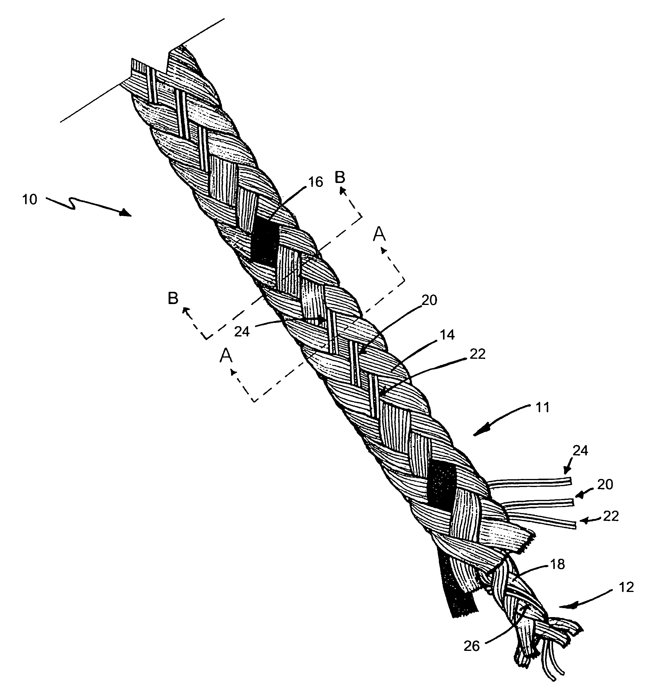
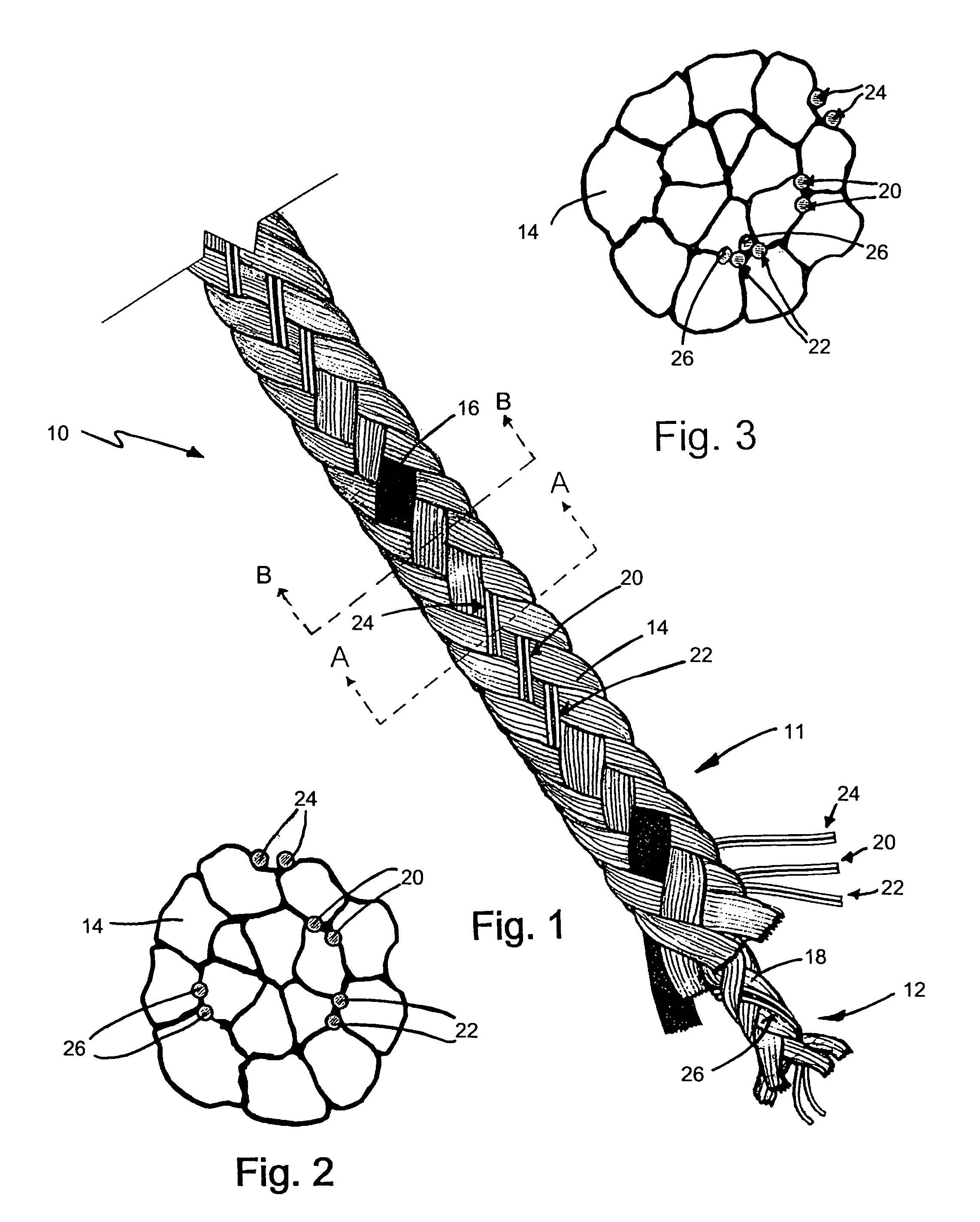
[0012]One aspect of the present invention relates to an electric rope designed to be strong, flexible and resilient to UV degradation and weathering caused by harsh climate conditions. The electric rope is lightweight and able to withstand the effects of damaged or broken conductive sections. An inner core and an outer sheath each comprise conductive elements braided with non-conductive elements. A tracer constructed of coloured non-conductive strands can be provided for visibility, the colour of which is chosen to contrast with the colour of the non-conductive elements in the outer sheath. Preferably the colour of the tracer is teal, which has been shown to be more UV resilient than other colours.
[0013]The braiding allows conductive elements of the outer sheath to periodically contact conductive elements of the inner core. The conductive elements in the outer sheath are intermittently exposed both on the surface of the sheath and on the interior of the sheath. When the outer sheath conductive elements are on the interior of the sheath, contact can occur with the conductive elements of the inner core, thereby maintaining or restoring conductivity in the outer sheath. In this manner, the conductive elements of the inner core provide conductivity throughout the length of the rope to overcome the effects of a breakage in the conductive elements of the outer sheath. The outer sheath serves to protect the inner core from the climate and to apply a shock to an animal upon contact.
[0015]A further aspect of the present invention teaches an electric rope comprising a plurality of non-conductive elements braided with at least one conductive element, wherein the conductive element is wound in a helical direction throughout the length of the rope. If two or more conductive elements are included, all the conductive elements are wound either clockwise or counterclockwise throughout the length of the rope, and each conductive element is wound with the same pitch, but longitudinally displaced from one another, thereby allowing the conductive elements to remain separate throughout the length of the rope.
[0016]Another aspect of the present invention teaches an electric rope comprising an inner core surrounded by an outer sheath. Bridging means exists to enable conductivity between the inner core and the outer sheath at intermittent intervals. The conductivity imparts electricity to the outer sheath at the intermittent intervals, while the bridging means circumvents any conductivity breakages in the outer sheath by enabling conductivity at the intermittent intervals that occur before and after the breakage.

Problems solved by technology

Permanent fences made of wood or metal are resilient, but require an expensive and complicated installation.
The ability to meet all of the above criteria is challenging for a fence typically constructed of weather-sensitive metal and pliable, degradable synthetic fibres.
Often, the metal wire becomes broken, either due to the collision of an animal with the fence or under deterioration caused by harsh climate conditions.
Upon breakage, the entire fence loses effectiveness as the electrical circuit is interrupted.
For example, copper has high conductivity, but is low in strength, prone to breakage and degrades quickly when exposed to outdoor climate conditions.
Additionally, the use of inexpensive, substandard polyester will usually cause deterioration of the fence within 24 months, which is a relatively short timeframe to require replacement of the fence.
Related to the type of metal and synthetic fibres used, the thickness of the fence must also be balanced with the weight of the fence since a thicker fence will withstand collision better, but will be heavy and may have installation issues.

Method used


Image

  • Electric rope
  • Electric rope

Examples


Embodiment Construction

[0020]The present invention is an animal containment and deterrent in the form of an electrically conductive rope for an electric fence. As shown in FIG. 1, the rope 10 comprises a braided outer sheath 11 and a braided inner core 12, each comprising a combination of non-conductive elements 14, 16 and 18, and conductive elements 20, 22, 24 and 26. The braid allows the sheath conductive elements 20, 22 and 24 to be exposed intermittently on the exterior and interior surfaces of the outer sheath 11. Accordingly, the core conductive elements 26 periodically contact the sheath conductive elements 20, 22 and 24 appearing on the interior surface of the outer sheath. In this manner, the electric rope is able to withstand the effects of broken conductive sections in the outer sheath 11 since the conductive elements 26 of the inner core 12 bridge contacts throughout the rope. The outer sheath 11 serves to protect the conductive elements 26 of the inner core 12 from degradation due to weatheri...


PUM

PropertyMeasurementUnit
lengthaaaaaaaaaa
lengthaaaaaaaaaa
conductivityaaaaaaaaaa

Abstract

This invention teaches a rope that can be electrified. The rope is comprised of an outer sheath and an inner core. The outer sheath includes non-conductive elements braided with one or more conductive elements. The conductive elements are wound in a parallel helical pattern and do not touch each other. The inner core is a braid comprising non-conductive and conductive elements. In both cores, the conductive elements comprise one or more metal strands and the non-conductive elements comprise one or more monofilaments of synthetic or natural fibers. Should a breakage occur in the conductive elements of the outer sheath, the conductive elements of the inner core provide conductivity across the breakage and throughout the length of the rope by intermittently contacting the conductive elements of the outer sheath. An optional colored tracer can be braided into the outer sheath to provide better visibility since the non-conductive elements are preferably a neutral color, such as white.

Description

[0001]This application claims the benefit of U.S. Provisional Application No. 60 / 511,109 filed Oct. 15, 2003.BACKGROUND OF THE INVENTION[0002]1. Field of the Invention[0003]This invention relates to a rope that provides electrical conductivity. In particular, the rope can be used as an electric fence to contain animals within an area or deter animals from entering an area.[0004]2. Background Information[0005]Several devices exist for the containment of animals. Permanent fences made of wood or metal are resilient, but require an expensive and complicated installation. Often a situation will necessitate a non-permanent fence, such as for restricting horses to graze in a portion of a field. Electric fences can be a non-permanent barrier or a long-term solution for cordoning off an area and providing an effective deterrent to contain livestock or exclude wildlife.[0006]Several criterion exist for the durability and characteristics of a good electric fence. Such a fence should withstand...

Claims


Application Information

Patent Timeline
Patent Type & Authority Patents(United States)
IPC IPC(8): D04C1/06A01K3/00H01B5/00H01B5/10
CPCA01K3/005D07B1/147H01B5/008H01B5/104D07B2201/1096
Inventor NOLAN, BRUCE
Owner NOLAN BRUCE
Why Eureka
Eureka Blog
Learn More