
Measurement of gas fuel amount

a gas fuel container and amount technology, applied in the direction of digital computer details, electric control, instruments, etc., can solve the problems of affecting the measurement accuracy of pressure and flow, the inability to use an amount gauge, and the inability to sense the amount accurately during vehicle movement, so as to improve the accuracy of weight measurement, and improve the accuracy of fuel amount measuremen

Inactive Publication Date: 2007-07-10
TOYOTA IND CORP
View PDF18 Cites 30 Cited by
  • Summary
  • Abstract
  • Description
  • Claims
  • Application Information

AI Technical Summary

Benefits of technology

This approach enhances the accuracy of fuel amount measurement in gas fuel containers, unaffected by temperature or vehicle motion, allowing for precise fuel level determination.

Problems solved by technology

However, with the prior art described above, fuel amount cannot be sensed accurately during vehicle motion.
Other methods known for use in sensing fuel amount in a gas fuel container include methods employing container internal pressure, cumulative fuel flow, or an amount gauge; however, where a gas fuel is used, it is not possible to use an amount gauge, and measurements of pressure and flow, which are affected by temperature changes, are not accurate either.

Method used


Image

  • Measurement of gas fuel amount
  • Measurement of gas fuel amount
  • Measurement of gas fuel amount

Examples


first embodiment

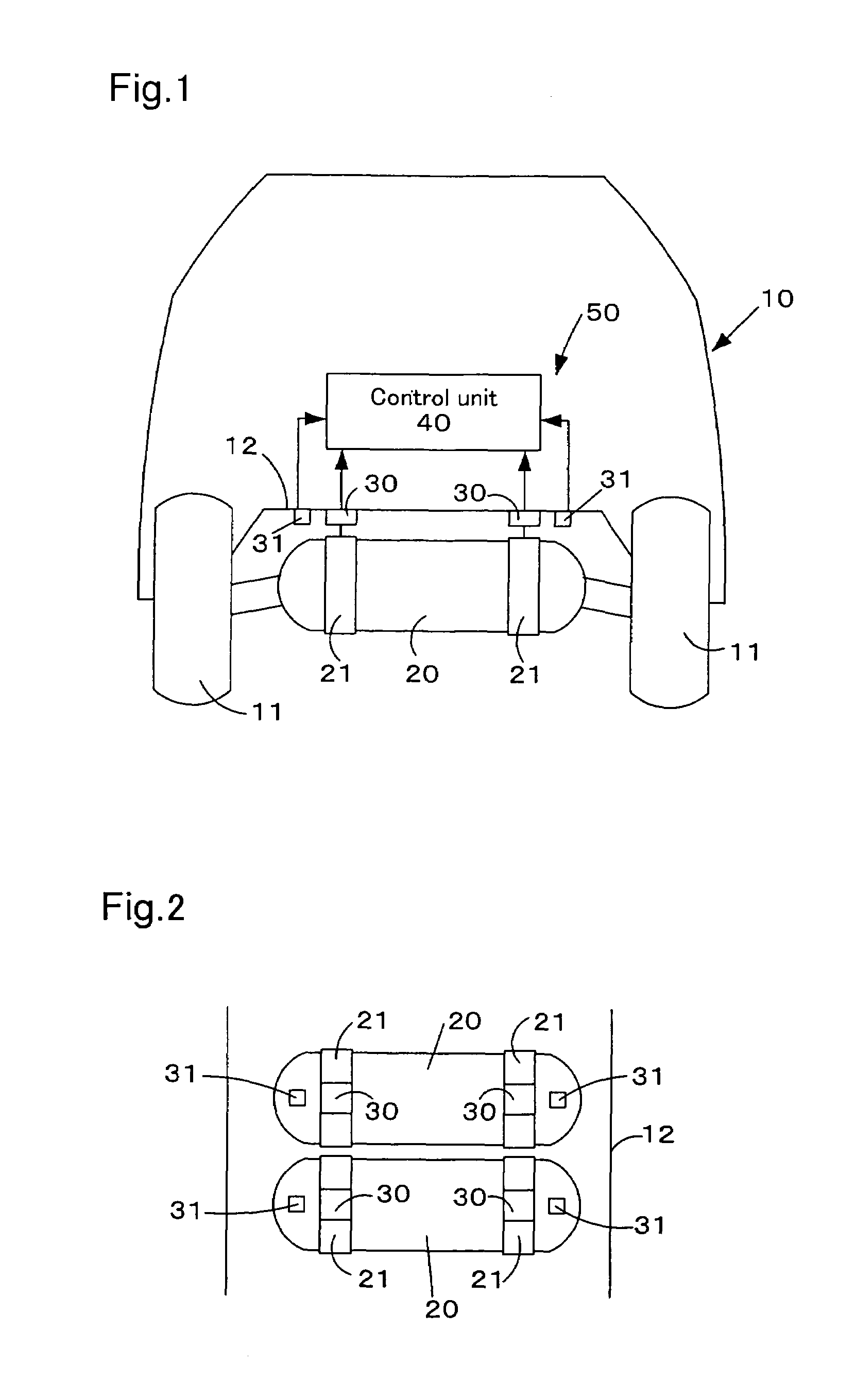
[0030]The following description of the general arrangement of a vehicle-mounted fuel container amount measuring apparatus pertaining to a first embodiment makes reference to FIGS. 1 to 4. FIG. 1 is a simplified illustration, viewed from the rear of the vehicle, of a vehicle-mounted fuel container amount measuring apparatus pertaining to a first embodiment. FIG. 2 is a simplified illustration, viewed from above the vehicle, of a vehicle-mounted fuel container amount measuring apparatus pertaining to the first embodiment. FIG. 3 is an illustration showing correspondence between hydrogen amount and weight measured by the vehicle-mounted amount measuring apparatus to the first embodiment. FIG. 4 is an illustration modeling vibration and sway (acceleration G) of a vehicle due to pitching and rolling.

[0031]As shown in FIG. 1 and FIG. 2, the vehicle 10 in this embodiment comprises two fuel containers 20 for storing hydrogen, disposed on the vehicle floor 12 inwardly from the wheels 11. Eac...

second embodiment

[0043]The following description of the general arrangement of a vehicle-mounted fuel container amount measuring apparatus pertaining to a second embodiment makes reference to FIGS. 6 to 8. FIG. 6 is a side view showing a simplified arrangement of the the weight sensor 30 and an acceleration sensor 32 making up the amount measuring apparatus 51 pertaining to a second embodiment. FIG. 7 is a model diagram showing characteristic features in the arrangement of the acceleration sensor 32 in the second embodiment. FIG. 8 is a flowchart showing a processing routine executed in the amount measuring process pertaining to the second embodiment.

[0044]The fuel container amount measuring apparatus pertaining to second embodiment is mounted on the vehicle 10 described first embodiment. As shown in FIG. 6, in the second embodiment a set of two fuel containers 20 is held together by a retaining strap 23. Each fuel container 20 is disposed on the vehicle floor 12 via the weight sensor 30. Other arra...


PUM


Abstract

A control unit 40 acquires acceleration α sensed by an acceleration sensor 31, and if the control unit 40 determines that acceleration α does not equal zero, the control unit 40 again acquires acceleration α. In the event that the control unit 40 decides that acceleration α equals zero, the control unit 40 acquires the weight M sensed by the weight sensor 30. The control unit 40 continues sampling of weight M until a predetermined sampling period has elapsed. Once the sampling period has elapsed, the control unit 40 calculates the average of weight M obtained through sampling, and uses the calculated average and a map to determine hydrogen amount.

Description

BACKGROUND OF THE INVENTION[0001]1. Field of the Invention[0002]The present invention relates to an amount measuring apparatus and an amount measuring method for measuring the remaining fuel amount in a fuel container.[0003]2. Description of the Related Art[0004]Where a fuel container is carried on board a vehicle, the sensed fuel amount may include error due to shifting occurring with vibration or acceleration and deceleration associated with motion of the vehicle, or with change in attitude of the vehicle. To solve this problem, there has been proposed a technique of waiting until the effects of vibration or the like associated with vehicle motion disappear (i.e. until the amount stabilizes) before reflecting a fuel amount value on the fuel gauge.SUMMARY OF THE INVENTION[0005]However, with the prior art described above, fuel amount cannot be sensed accurately during vehicle motion.[0006]Other methods known for use in sensing fuel amount in a gas fuel container include methods empl...

Claims


Application Information

Patent Timeline
Patent Type & Authority Patents(United States)
IPC IPC(8): G01F23/20G01G23/01B60K15/03B60K15/077B60K15/10F02D45/00F02M37/00G01G17/04G01G19/03G01G19/08G01G19/12
CPCG01F23/20B60K2015/03217
Inventor KIMBARA, MASAHIKOMORI, DAIGORONITO, TAKEHIROKUBO, HIDEHITOTSUZUKI, MAKOTO
Owner TOYOTA IND CORP
Learn More