
Method and associated system for recording and retrieving fabrication and/or fitting data associated with a prosthetic component

a technology for prosthetic components and data, applied in the field of method and associated system for recording and retrieving fabrication and/or fitting data associated with prosthetic components, can solve the problems of creating errors that are not easily detected and out of the control of the practitioner, and patients often wait weeks for new sockets

Inactive Publication Date: 2007-07-03
PROSTHETIC DESIGN
View PDF12 Cites 21 Cited by
  • Summary
  • Abstract
  • Description
  • Claims
  • Application Information

AI Technical Summary

Benefits of technology

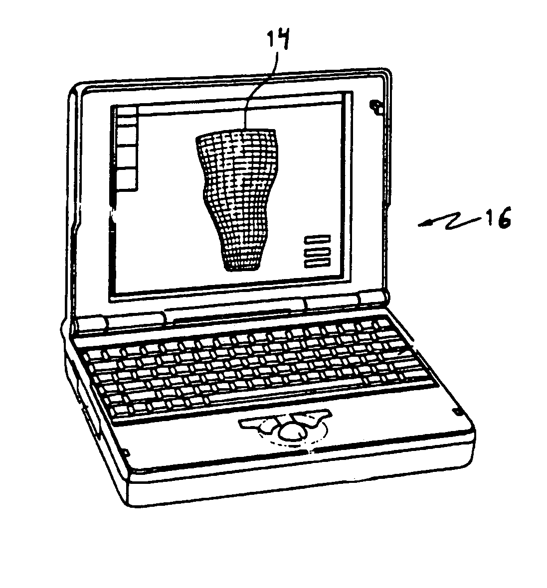
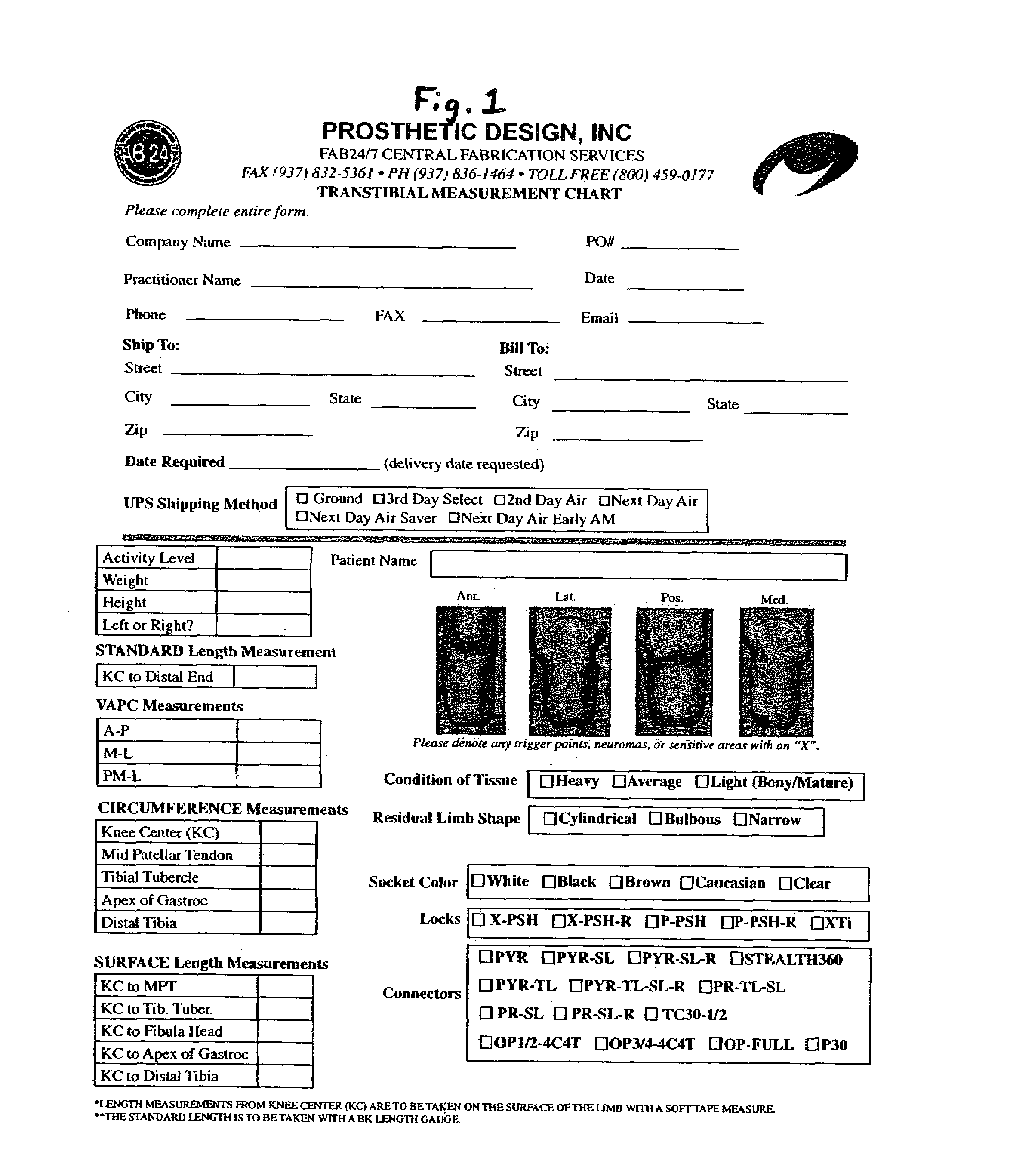
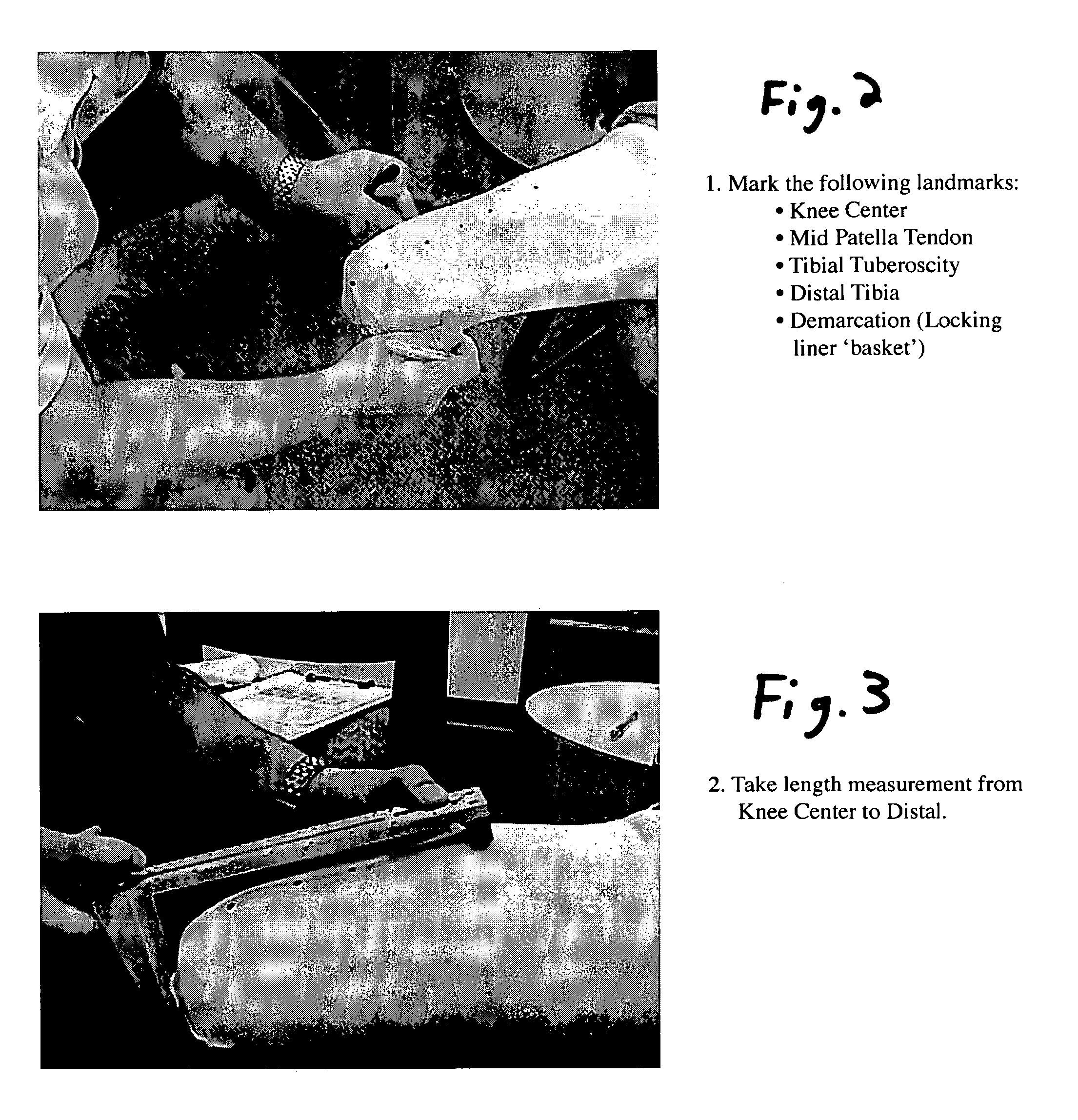
[0005]It is a first aspect of the present invention to provide a method of socket design and fabrication for Below-the-Knee (BK) amputees that utilizes manual measurements. This method, known as BK by Measurement, utilizes a manual measurement procedure where predetermined points are identified and measurements are taken of a patient's residual limb. These measurements are recorded and thereafter entered into a software package enabling customization by the fabrication facility. Prosthetic components fabricated in accordance with the present invention provide a custom fit, while not relying on more expensive digital imaging technology.
[0006]It is a second aspect of the present invention to provide a method and associated system for recording and retrieving fabrication and / or fitting data associated with a prosthetic component for use with a particular patient and; more specifically, to a method and associated system associating a unique indicia with a patient's prosthetic component that allows for identification and retrieval of the fabrication and / or fitting data associated with a prosthetic component, so as to facilitate manufacturing and / or fitting a new prosthetic component for the patient.

Problems solved by technology

Before CAD / CAM became commonplace in the industry, practitioners relied on labor-intensive methods involving plaster casts and heavy plaster models that resulted in patients often waiting weeks for new sockets.
Such devices, while often creating a highly accurate digital representation of the residual limb, could potentially create errors undetectable and out of the control of the practitioner.
In addition, the costs involved with using CAD devices are often prohibitive, especially when calculating the high costs in dollars and time spent learning the CAD design techniques.

Method used


Image

  • Method and associated system for recording and retrieving fabrication and/or fitting data associated with a prosthetic component
  • Method and associated system for recording and retrieving fabrication and/or fitting data associated with a prosthetic component
  • Method and associated system for recording and retrieving fabrication and/or fitting data associated with a prosthetic component

Examples


Embodiment Construction

[0039]It should be understood that the following detailed description of embodiments of the present invention are exemplary in nature and are not intended to constitute limitations upon the present invention. It is also to be understood that variations of the exemplary embodiments contemplated by one of ordinary skill in the art shall concurrently fall within the scope and spirit of the invention.

[0040]As shown in FIG. 24, the exemplary embodiments of the present invention may utilize a business model for the fabrication and fitting of prosthetic limbs and prosthetic limb components involving a central fabrication facility 100 and plurality of remote prosthetist offices or facilities 102. The central fabrication facility 100 is able to communicate electronically to each of the remote offices (and vice versa) through a data link such as the Internet. In this model the central fabrication facility 100 has equipment, such as carvers and thermoformers for fabricating certain prosthetic ...


PUM


Abstract

A method of socket design and fabrication for Below-the-Knee (BK) amputees that utilizes manual measurements. This method, known as BK by Measurement, utilizes a manual measurement procedure where predetermined points are identified and measurements are taken of a patient's residual limb. These measurements are recorded and thereafter entered into a software package enabling customization by the fabrication facility. Prosthetic components fabricated in accordance with the present invention provide a custom fit, while not relying on more expensive digital imaging technology. The invention also provides a method and associated system for recording and retrieving fabrication and / or fitting data associated with a prosthetic component for use with a particular patient, which can include affixing to the prosthetic component a strip debossed with indicia unique to the particular patient or prosthetic component.

Description

CROSS-REFERENCE TO RELATED APPLICATIONS[0001]This application claims the benefit of U.S. Provisional Patent Application Ser. No. 60 / 609,903, filed Sep. 14, 2004, and U.S. Provisional Patent Application Ser. No. 60 / 590,058, filed Jul. 21, 2004. The disclosure of each of these provisional applications is incorporated herein by reference.BACKGROUND[0002]Starting in the early 1990s, many Orthotic and Prosthetic (O&P) care professionals saw trends that pointed to a rapid increase in the population of amputees due mainly to longer life spans of existing amputees and an increasing number of people facing risk factors that lead to amputations. Those trends led to the desire for computer-aided design and manufacturing (CAD / CAM) to help the practitioners reduce time spent on patient care, while increasing the quality of that care. Before CAD / CAM became commonplace in the industry, practitioners relied on labor-intensive methods involving plaster casts and heavy plaster models that resulted in...

Claims


Application Information

Patent Timeline
IPC IPC(8): G05B19/4097G06F19/00G05B19/4099
CPCA61B5/107A61B5/4528A61F2/5046A61F2/80A61B5/4523A61F2002/30714A61F2002/5047A61F2002/505A61F2002/5053A61F2250/0086A61F2250/0089G06F19/3437Y10S623/901A61F2002/3071G16H50/50
Inventor SLEMKER, TRACY C.HOSKINS, ROBERTBUSCH, LUCINDASCHALL, SCOTT R.SIMMONS, RALPH
Owner PROSTHETIC DESIGN
Learn More