
Tamper resistant pin entry apparatus

a technology of entry apparatus and pins, which is applied in the direction of contact mechanisms, snap-action arrangements, instruments, etc., can solve problems such as damage to storage media, and achieve the effect of preventing information leakag

Active Publication Date: 2007-07-03
NAUTILUS HYOSUNG
View PDF6 Cites 925 Cited by
  • Summary
  • Abstract
  • Description
  • Claims
  • Application Information

AI Technical Summary

Benefits of technology

"The present invention provides a way to protect a PIN entry apparatus in cash transaction machines or ATMs from hacking. An apparatus is provided that includes a key module, a key scan board, a rear case, and an electric circuit section. The electric circuit section includes a memory that can store important information. The apparatus can detect changes in the memory caused by hacking or unauthorized access and prevent the information from being leaked. The electric circuit section can also make the stored information unreadable by deleting the power supply to the memory. The apparatus includes a metal plate to physically protect the key scan board from tampering. The electric circuit section can also include a circuit connector and a board connector to transmit the states of connection at the contacts to the electric circuit. The apparatus can detect changes in the voltage or electric current caused by the removal of the key module or rear case. The key scan board and rear case can be easily connected and disconnected. Overall, the invention provides a way to protect important information in cash transaction machines or ATMs from hacking."

Problems solved by technology

In addition, the electric circuit section may produce a control module easily by using a microcontroller, and damage the storage medium by enabling the control module to control a power generator that generates the voltage or electric current.

Method used


Image

  • Tamper resistant pin entry apparatus
  • Tamper resistant pin entry apparatus
  • Tamper resistant pin entry apparatus

Examples


Embodiment Construction

[0059]Hereinafter, exemplary embodiments of the present invention will be more fully described with reference to the accompanying drawings. This invention may, however, be embodied in many different forms and should not be construed as limited to the embodiments set forth herein; rather, these embodiments are provided so that this disclosure will be thorough and complete, and will fully convey the scope of the invention to those skilled in the art. Like reference numerals refer to similar or identical elements throughout.

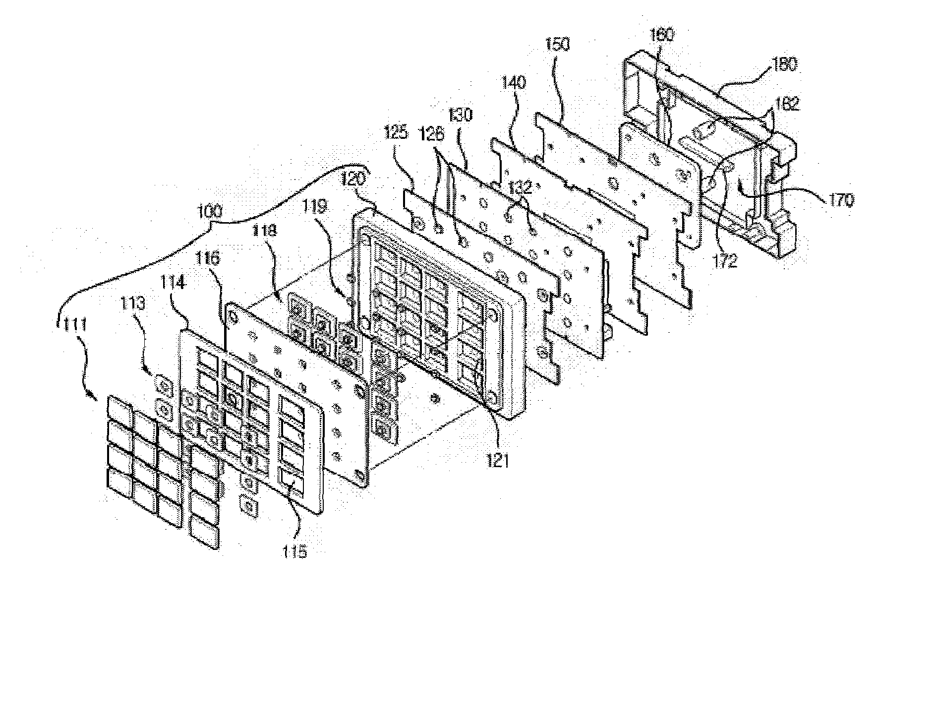
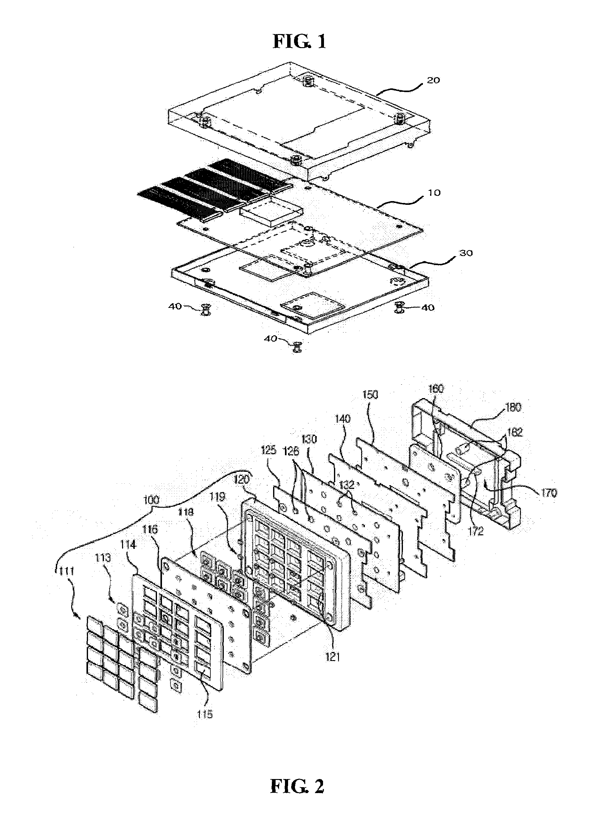
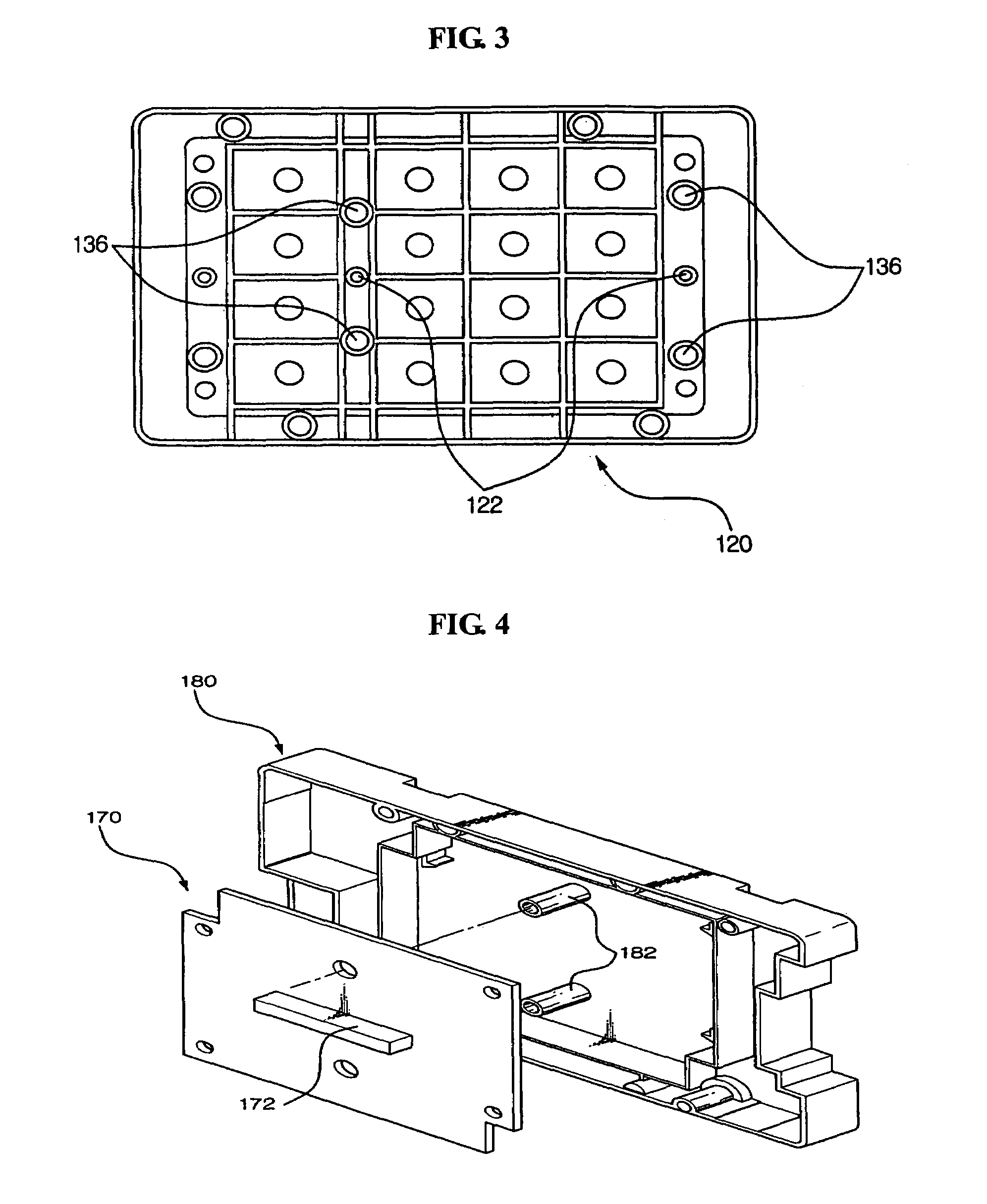
[0060]FIG. 2 is a perspective view illustrating an apparatus for protecting a PIN pad module according to one embodiment of the present invention; FIG. 3 is a plan view illustrating the rear of a bezel base according to one embodiment of the present invention; FIG. 4 is a partial perspective view illustrating an apparatus for protecting a PIN pad module according to one embodiment of the present invention; FIG. 5 is a sectional view illustrating an apparatus for pro...


PUM


Abstract

Disclosed is a tamper resistant PIN entry apparatus for input of a key and for encryption of a password in a cash transaction machine. The PIN entry apparatus supplies the electric power to a memory of an electric circuit section, in such a manner that a first rod and a second rod of a rear case connect contacts of a key scan board, wherein the first rod is protruded on the rear of a key module including a button provided substantially on the front of the key module and the second rod of the rear case is coupled with the rear of the key module. At this time, in case that the rear case is removed from the key module or damaged, thereby changing the location of any one of the first and the second rods at the contact, the electric circuit section detects the event and destroys the memory itself physically. Otherwise, the electric circuit section makes information stored in the memory physically or softwarely unreadable, thereby preventing the leakage of the information.

Description

CROSS REFERENCE TO RELATED APPLICATION[0001]This application claims priority under 35 USC § 119 to Korean Patent Application No. 2004-92464 filed on Nov. 12, 2004, the contents of which are incorporated herein by reference in its entireties.BACKGROUND OF THE INVENTION[0002]1. Field of the Invention[0003]The present invention relates to an apparatus for entering a Personal Identification Number (hereinafter, PIN) in a cash transaction machine. More particularly, the present invention relates to a PIN entry apparatus for protecting a PIN and encrypting a user's valuable information in a cash transaction machine (terminal), and relates to a tamper resistant PIN entry apparatus in which the apparatus, in case that the PIN entry apparatus is disassembled to hack into a password, detects the event, makes the password or key data unreadable, and in case that a key pad is to be partially incised, prevents hacking of the password by disabling the incision.[0004]2. Description of the Related ...

Claims


Application Information

Patent Timeline
Patent Type & Authority Patents(United States)
IPC IPC(8): H01H3/16
CPCG07F7/10G07F7/1066H01H13/702H01H2209/07H01H2223/002H01H2231/006H01H2239/002H01H2239/032G07F19/00
Inventor KIM, BO SOONJANG, HYUN SOOLEE, SEUNG CHAN
Owner NAUTILUS HYOSUNG
Learn More