
Support structure

a support structure and support rod technology, applied in the direction of floating buildings, non-magnetic metal hulls, hull reinforcements, etc., can solve the problems of limiting access to machinery, affecting the operation of the support structure, and affecting the operation of the machine itsel

Inactive Publication Date: 2007-07-03
AUSTAL SHIPS
View PDF6 Cites 2 Cited by
  • Summary
  • Abstract
  • Description
  • Claims
  • Application Information

AI Technical Summary

Problems solved by technology

One means of reducing vibration is to further increase the size of the support structure and this can be a particular problem where the ship is constructed of aluminum in order to obtain light weight.
The support structure that is thus used to support auxiliary machinery usually limits access to the machinery especially access to the machinery services that are frequently located on the underside of the machinery such as electrical cabling, cooling water and fuel supplies.
Furthermore, access to the mounting bolts and the machines themselves can be difficult because of the substantial nature of the support structure.
On high speed light weight craft engine rooms are usually congested because the need for high speed results in very large power units and thus physically large engines and associated transmission systems.
In multi hulled vessels this is a particular problem due to the narrowness of the hulls and yet the need for an engine room that can house a power unit of substantial size.

Method used


Image

  • Support structure
  • Support structure
  • Support structure

Examples


Embodiment Construction

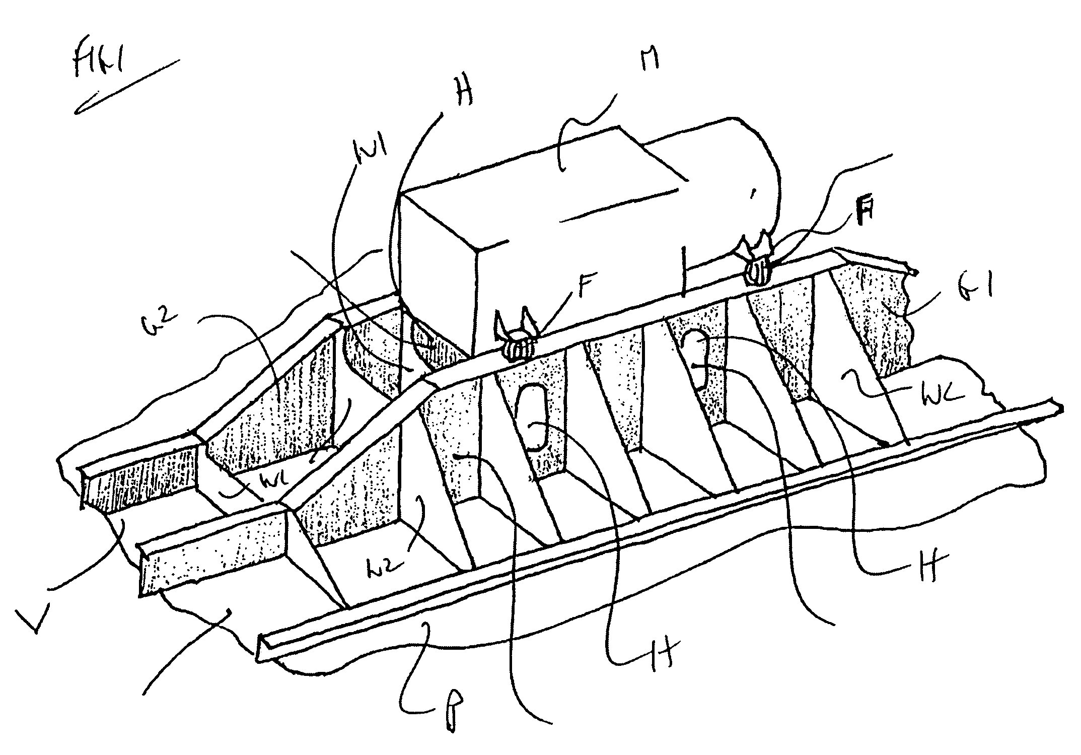
[0017]A conventional installation of auxiliary machinery M is shown in FIG. 1 in which the auxiliary machinery M is supported in an elevated configuration by a pair of spaced girders G1 and G2 via flexible mounts F positioned at each corner of the machinery. The auxiliary machinery M spans the two girders which are welded to project in a parallel array upwardly from the bottom plating P of the vessel V. A series of interconnecting webs W join the girders G1 and G2 and lateral support webs W2 extend from the sides of the girders to the plating P. A series of access holes H are provided along the girders and the webs to provide access to the underside of the auxiliary machinery M. However this is a cumbersome arrangement with very difficult and limited access that has proved unsatisfactory in practice.

[0018]In the embodiment shown in FIGS. 2 to 5, a trussed frame 10 is used to support a rectangular horizontal plate 11 which in turn supports the auxiliary machinery M via flexible mount...


PUM


Abstract

A support structure for auxiliary machinery in a seagoing vessel, the support structure comprising a trussed frame supporting a mounting plate at an elevated height above the bottom or deck of the vessel, the mounting plate being adapted to support auxiliary machinery, the trussed frame comprising beams arranged in triangles along the sides and ends of the frame, whereby the frame elevates the machinery and provides ready access to the underside of the machinery.

Description

INTRODUCTION[0001]This invention relates to a support structure for use with auxiliary machinery in a sea going vessel. More particularly the invention relates to a support structure to support auxiliary machinery used in a multi hulled passenger and vehicle carrying sea going vessel.BACKGROUND OF THE INVENTION[0002]Sea going vessels are usually propelled by large diesel engines that are housed within the hull of the vessel to drive one or more propulsion systems at the stern of the vessel via drive shafts that are located in housings that extend from the engine or engines. Such vessels also have a requirement for auxiliary machinery, that is machinery that is driven off the internal combustion engines or turbines to power generators, pumps and a variety of other componentry that is conventional in vessels of this kind.[0003]Because this auxiliary machinery is driven by, for example, diesel engines and there is a considerable transfer of force from the diesel engines to the auxiliar...

Claims


Application Information

Patent Timeline
Patent Type & Authority Patents(United States)
IPC IPC(8): B63B3/00
CPCB63B3/70
Inventor ARMSTRONG, NEVILLE A.MURRAY, WAYNE
Owner AUSTAL SHIPS
Learn More