Apparatus and method for generating pulses

a pulse and apparatus technology, applied in the direction of pulse technique, generating/distributing signals, instruments, etc., can solve the problems of floating nodes, inability to maintain circuit values, and rely on capacitance alone at nodes to maintain circuit values

Active Publication Date: 2007-06-26
TEXAS INSTR INC
View PDF4 Cites 9 Cited by
  • Summary
  • Abstract
  • Description
  • Claims
  • Application Information

AI Technical Summary

Benefits of technology

[0006]It is, therefore, an object of the present invention to provide an apparatus and method for generating pulses that is compact and involves no floating nodes.

Problems solved by technology

A problem with such prior art devices has been floating nodes (see FIG. 1).
Reliance on capacitance alone at a node to maintain circuit values such as a predetermined voltage is not reliable because without actively maintaining the desired value at the node, the charge will bleed off.
Today's circuitry operates at sufficiently fast speeds that there is insufficient capacity at circuit nodes to maintain the desired logic values (e.g., voltage values) without driving the node.
The circuit nodes cannot reliably maintain the required circuit values and, as a consequence, the circuit performance is also unreliable.
This unreliability may be manifested, for example, in spurious pulses or truncated pulses from unpredictable coupling with a node.
Said another way, unpredictable coupling with a node or unpredictable charging or discharging of a node in a circuit may cause the circuit to generate pulses having unpredictable shape or duration or other unpredictable characteristics.

Method used


Image

  • Apparatus and method for generating pulses
  • Apparatus and method for generating pulses
  • Apparatus and method for generating pulses

Examples


Embodiment Construction

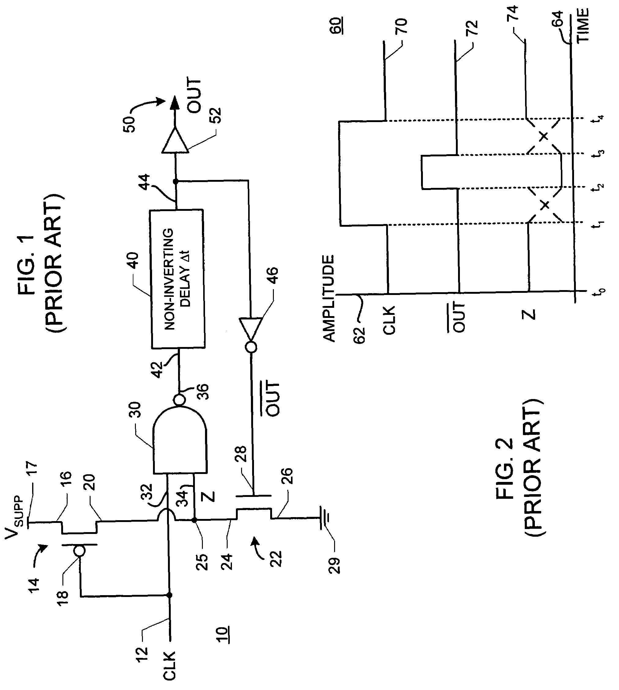
[0014]FIG. 1 is a schematic diagram of a representative prior art pulse generating apparatus. In FIG. 1, a pulse generating apparatus 10 receives a clock signal CLK at an input locus 12. Input locus 12 is coupled with a PMOS transistor 14. PMOS transistor 14 has a source 16 coupled with a supply voltage locus 17, a gate 18 coupled with input locus 12 and a drain 20 coupled with an NMOS transistor 22. NMOS transistor 22 has a source 24 coupled with drain 20 of PMOS transistor 14, a drain 26 coupled with ground 29 and a gate 28.

[0015]A logic gate 30 has a first logic input locus 32 coupled with input locus 12 and a second logic input locus 34 coupled at a node 25 with drain 20 of PMOS transistor 14 and source 24 of NMOS transistor 22. Clock signal CLK is therefore present at first logic input locus 32. Second logic input locus 34 is indicated as carrying a signal Z for purposes of describing operation of apparatus 10. Logic gate 30 has a logic output locus 36 connected with a delay un...


PUM


Abstract

An apparatus for generating pulses includes: (a) A delay unit having an input delay locus for receiving a delay unit input signal and an output delay locus for presenting an output delay signal. The delay unit output signal is delayed by a delay interval with respect to the input delay signal. (B) A latch coupled with the delay unit to selectively keep the delay unit input signal at at least one predetermined signal level.

Description

BACKGROUND OF THE INVENTION[0001]The present invention is directed to pulse generating apparatuses. Pulse generation is an important function for many electrical devices and products. Pulses are used for many purposes including, by way of example and not by way of limitation, driving pulse width modulation circuitry. Pulses provided must be of predictable and consistent duration and period to provide a reliable timing circuit or modulating circuit or other feature of a product using the pulses.[0002]Some prior art pulse generating apparatuses used long chains of series-connected delay units, known as delay chains, to establish desired delay intervals for generating pulses. However, in today's products there is a trend toward requiring smaller more compact circuitry and minimizing die space or “real estate” required by a circuit or apparatus is a design objective of increasing importance. One response has been to use a feed forward circuit arrangement by which a delay chain is used t...

Claims


Application Information

Patent Timeline
Patent Type & Authority Patents(United States)
IPC IPC(8): H03K3/13
CPCH03K5/135H03K2005/00293
Inventor BRANCH, CHARLES M.BARTLING, STEVEN C.
Owner TEXAS INSTR INC
Why Eureka
Try Eureka