
Motor vehicle door lock

a technology for motor vehicles and door locks, applied in the direction of locking devices, mechanical devices, fastening means, etc., can solve the problems of aforementioned blocking operation, high possibility of jamming, and the association of the drive with an unwanted striking noise, so as to reduce the tendency to jam and reduce the striking noise

Active Publication Date: 2007-06-26
BROSE SCHLIESSSYSTEME GMBH & CO KG
View PDF9 Cites 19 Cited by
  • Summary
  • Abstract
  • Description
  • Claims
  • Application Information

AI Technical Summary

Benefits of technology

[0007]An object of the present invention is directed to a motor vehicle door lock that has a reduced striking noise associated with a blocking operation of the drive as well as a reduced tendency to jam.
[0008]One way in which the aforementioned object is achieved is through use of the motor vehicle door lock of the present invention. A door lock with latching elements such as a latch and ratchet with a lock mechanism is provided. The lock mechanism has a drive that includes a drive motor, or the like, and an actuating element. The ratchet can be raised by the drive, and the ratchet thus moves into an action area of the drive so that the ratchet can block further movement of the drive. Thus, the movement of the ratchet can turn off the drive in a block operation. The ratchet, viewed in a “kinematic chain” from the drive motor to the actuating element, engages the drive to block in front of the actuating element and not on the actuating element itself (without directly engaging the actuating element). The engagement point of the ratchet in the kinematic chain has the advantage that the blocking, which is necessary for blocking operation, takes place at the point at which the active torque is comparatively low. Thus, this results in a reduced striking noise as well as a reduced tendency to jam.
[0009]In accordance with another exemplary embodiment of the invention, with respect to the output of the drive motor, the active torque is less than the torque acting on the actuating element. Additionally, the configuration of a step-down gearing with a worm and worm wheel leads to a durable configuration.

Problems solved by technology

One problem with the known motor vehicle door lock is that the blocking of the drive is associated with an unwanted striking noise.
Furthermore, the application of a comparatively high torque to the actuating element leads to a higher possibility of jamming during aforementioned blocking operation.

Method used


Image

  • Motor vehicle door lock
  • Motor vehicle door lock
  • Motor vehicle door lock

Examples


Embodiment Construction

[0024]A motor vehicle door lock, for the purposes of the present invention, can include a side door lock, a hood lock or a hatch lock of a motor vehicle body.

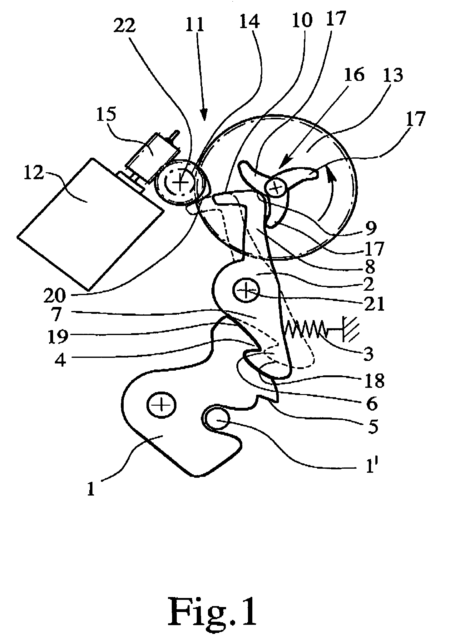
[0025]FIG. 1 depicts a lock latch 1 and a ratchet 2 employed within a motor vehicle door lock. The ratchet is pretensioned, for example, by a spring 3 and is associated with the latch 1. The latch 1 can be moved into an open position, into a preliminary catch position and into a main catch position. For this purpose, the latch 1 has a preliminary catch 4 and a main catch 5. The latch 1 is shown in the preliminary catch position in FIG. 1. Here, the latch 1 interacts in a conventional manner with a locking pin 1′. Further discussion of the preliminary catch position can be omitted since it is irrelevant to the present invention.

[0026]The ratchet 2 has a hook-shaped recess 6 which can engage the preliminary catch 4 or the main catch 5 and keep the latch 1 in its respective position. For this purpose, the latch 1 is likewise prete...


PUM


Abstract

A motor vehicle door lock with latching elements, such as a latch and a ratchet and with a lock mechanism. The lock mechanism has a drive, the drive having a drive motor, or the like, and an actuating element. The ratchet can be raised by the drive, so that the ratchet moves into an action area of the drive, such that continued motion of the drive is blocked by the ratchet. Thus, the drive can be turned off in a blocking operation. The ratchet, viewed in the kinematic chain from the drive motor to the actuating element, is engaged to the drive for blocking in front of the actuating element but not on the actuating element.

Description

BACKGROUND OF THE INVENTION[0001]1. Field of the Invention[0002]This invention relates generally to a motor vehicle door lock, and more specifically to a motor vehicle door lock with latching elements such as a latch and ratchet with a lock mechanism. The lock mechanism has a drive with a drive motor and an actuating element and the ratchet able to be raised by the drive. Also, this invention relates generally to a drive for a motor vehicle door lock with at least one displaceable operating element such as a ratchet.[0003]2. Description of Related Art[0004]A motor located in motor vehicle door locks can be utilized to perform an opening assist function (i.e., a lifting of the ratchet) and a central interlock function. For implementation of these functions triggered by a motor, a drive, a drive motor and an actuating element are employed. An displaceable operating element, assigned to each respective function, can be actuated. For example, in the case of the opening assist function, ...

Claims


Application Information

Patent Timeline
Patent Type & Authority Patents(United States)
IPC IPC(8): E05C3/06E05B65/12
CPCE05B81/14Y10T292/1047Y10T292/1082
Inventor KACHOUH, CHECRALLAH
Owner BROSE SCHLIESSSYSTEME GMBH & CO KG
Learn More