
Method and apparatus for magnetic resonance imaging incorporating a spiral coil

a magnetic resonance imaging and spiral coil technology, applied in the field of magnetic resonance imaging systems, can solve the problems achieve the effect of increasing the signal-to-noise ratio (snr), shortening the time, and highly desirable results

Inactive Publication Date: 2007-06-19
INVIVO CORP
View PDF32 Cites 6 Cited by
  • Summary
  • Abstract
  • Description
  • Claims
  • Application Information

AI Technical Summary

Benefits of technology

[0006]In additional embodiments, additional coils can be added and can be isolated as well, with all the coils optionally in quadrature. For eample, a non-rotated, a 2π rotated, and a −2π rotated birdcage coil can all be isolated from each other. This can result in an increased signal-to-noise ratio (SNR). Also, the subject invention can allow easy partially parallel imaging (e.g., SENSE and SMASH) due to the linear phase difference from one end of the coil channels to the other. The subject coil designs can produce highly desirable results for these partially parallel imaging techniques and can allow shortening of the time needed for imaging and / or allow for faster real-time imagery.

Problems solved by technology

This can result in an increased signal-to-noise ratio (SNR).

Method used


Image

  • Method and apparatus for magnetic resonance imaging incorporating a spiral coil
  • Method and apparatus for magnetic resonance imaging incorporating a spiral coil
  • Method and apparatus for magnetic resonance imaging incorporating a spiral coil

Examples


Embodiment Construction

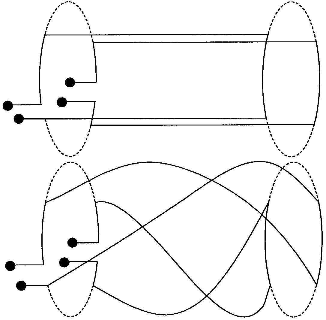
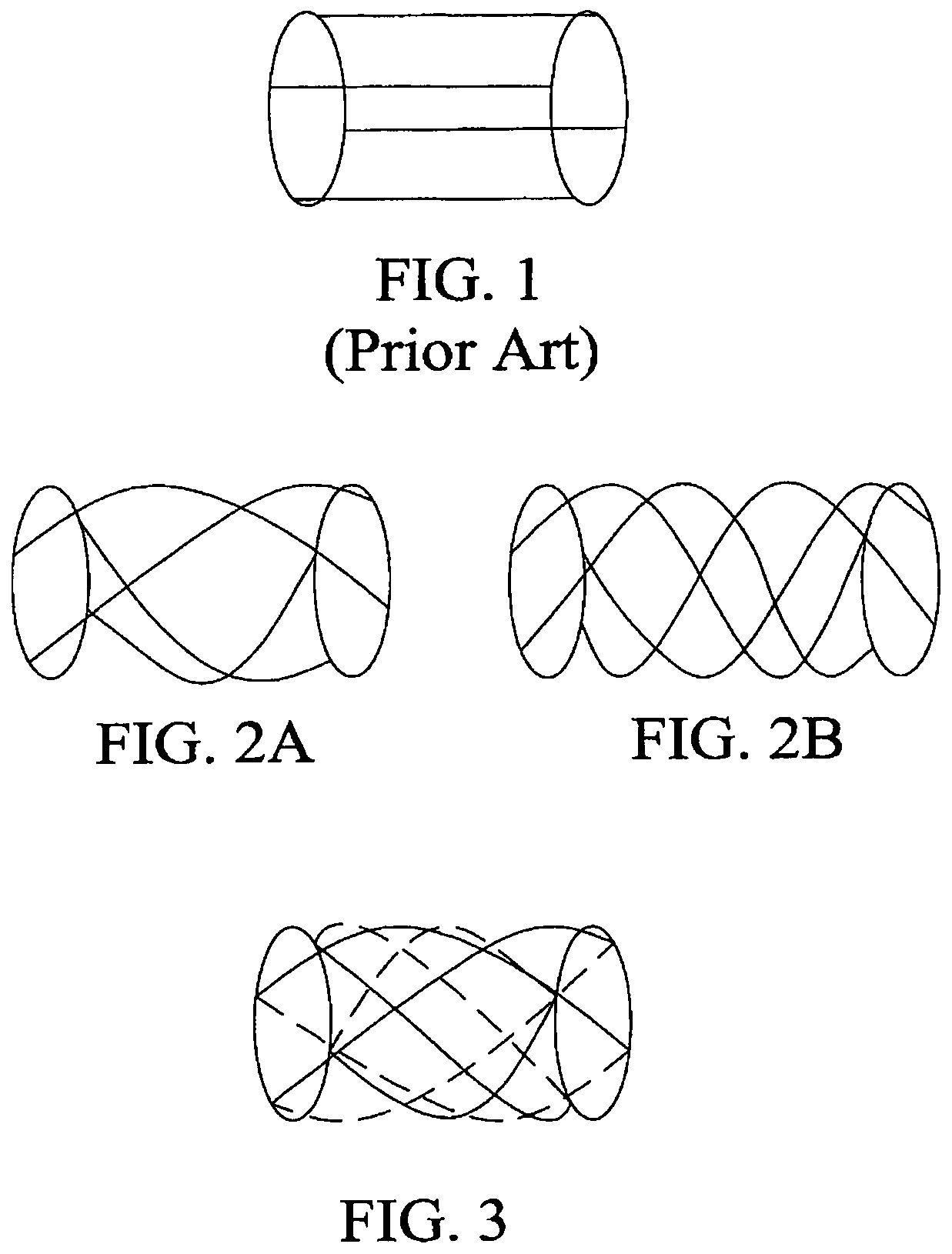
[0022]The subject invention pertains to a method and apparatus utilizing one or more spiral coils, such as spiral birdcage coils, spiral Alderman-Grant (Alderman, D. W. and Grant, D. M., Jo. Magnetic Resonance 36:447 [1979]) type of coil, spiral saddle coils, Helmholtz coil pairs, and other spiral volume and spiral surface coils. The spiral coils of the subject array can be substantially isolated from each other while covering nearly the same volume or surface. Examples of surface coils include, but are not limited to, one coil of a Helmholtz pair of coils. For cylindrical geometrics, isolation can be enhanced by having the rotation, or change in direction from one end of the coil to the other, be 2nπ, where n is an integer.

[0023]In additional embodiments, additional coils can be added and can be isolated as well, with all the coils optionally in quadrature. This can result in an increased signal-to-noise ratio (SNR). Also, the subject invention can allow partially parallel imaging ...


PUM


Abstract

The subject invention pertains to a method and apparatus utilizing one or more spiral coils, such as spiral birdcage coils, spiral saddle coils, Helmholtz coil pairs, and other spiral volume and spiral surface coils. The spiral coils of the subject array can be substantially isolated from each other while covering nearly the same volume or surface. For cylindrical geometrics, isolation can be enhanced by having the rotation, or change in direction from one end of the coil to the other, be 2nπ, where n is an integer.

Description

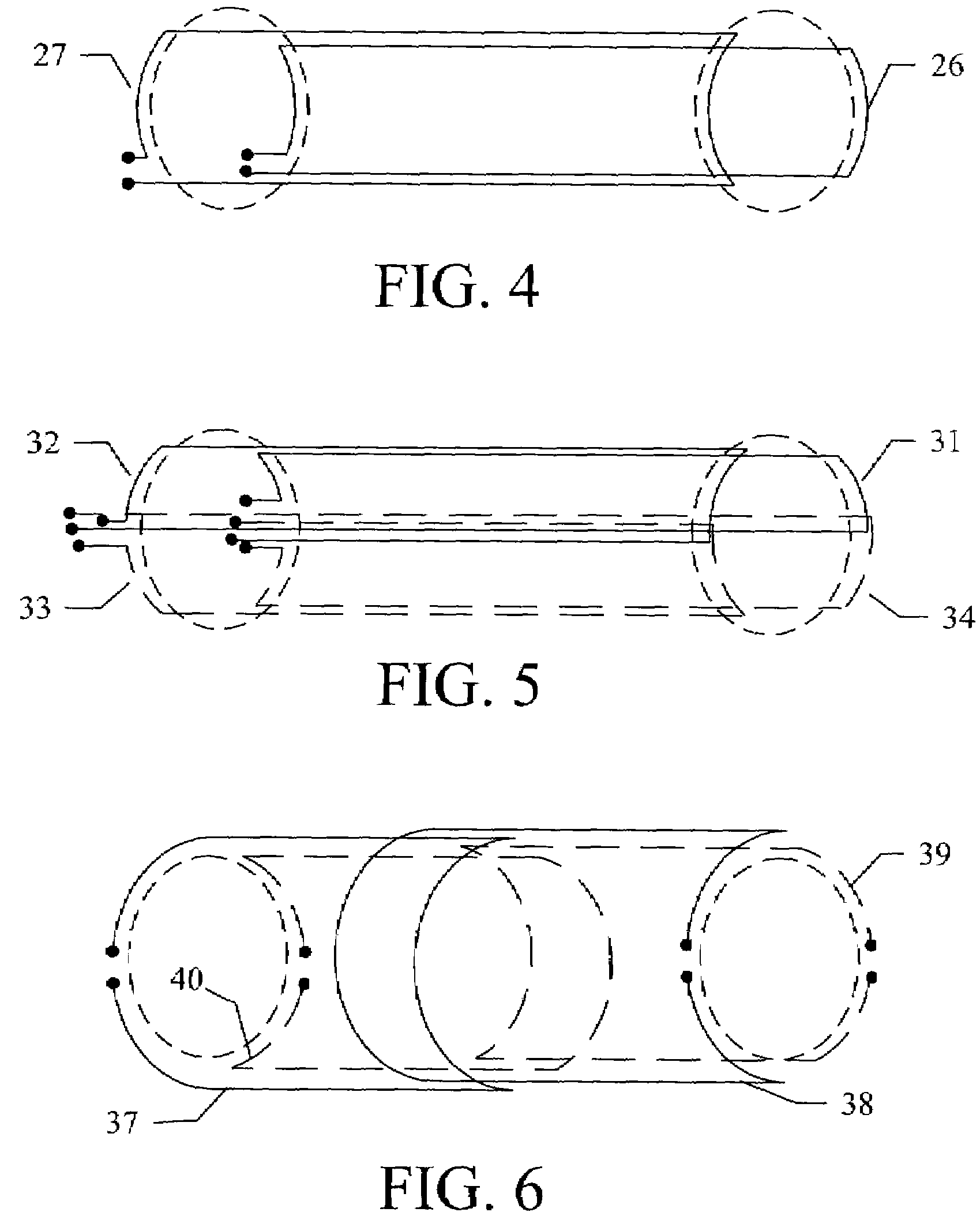
CROSS-REFERENCE TO RELATED APPLICATION(S)[0001]The present application claims the benefit of U.S. Provisional Patent Application Ser. No. 60 / 306,962; filed Jul. 20, 2001, which is hereby incorporated by reference herein in its entirety, including any figures, tables, or drawings.BACKGROUND OF INVENTION[0002]The present invention relates to magnetic resonance imaging (MRI) systems. Receiving coils are used in MRI systems to intercept the radio frequency magnetic field generated by a human subject or object in the presence of a main magnetic field. Many coil designs exist for use in MRI systems, including what is often referred to as a “birdcage” coil. The birdcage coil has been described in the Journal of Magnetic Resonance (1985) 63:622-628 and U.S. Pat. No. 4,680,548 to Edelstein et al. FIG. 1 shows a standard birdcage coil having four conductive connection members connecting two circular conductive loops. Although four conductive connection members have been shown in FIG. 1, other...

Claims


Application Information

Patent Timeline
Patent Type & Authority Patents(United States)
IPC IPC(8): G01V3/00G01R33/34G01R33/341
CPCG01R33/34046G01R33/341
Inventor DUENSING, G. RANDY
Owner INVIVO CORP
Learn More