
Optoelectronic arrangement having a laser component, and a method for controlling the emitted wavelength of a laser component

a technology of optoelectronic arrangement and laser component, which is applied in the direction of optics, optical elements, instruments, etc., can solve the problems of requiring a relatively large electric power, reducing the efficiency of the system, so as to achieve the effect of allowing the wavelength stabilization of the laser diode and being simple and cost effectiv

Inactive Publication Date: 2007-06-19
INFINEON TECH AG
View PDF4 Cites 3 Cited by
  • Summary
  • Abstract
  • Description
  • Claims
  • Application Information

AI Technical Summary

Benefits of technology

The invention provides an optoelectronic arrangement that includes a laser component, a cooling device, a device for direct optical detection of the emitted wavelength of the laser component, and a package with a small design. This arrangement allows for the stabilization of the wavelength of the laser component in small form factor transceivers. The device for direct optical detection generates a signal that is used to control the cooling device, ensuring a constant operating point of the laser component. The cooling device is preferably a prefabricated micro-Peltier cooler chip mounted on a solid base or a separate submount. The optoelectronic arrangement is housed in a hermetically sealed housing. The technical effects of the invention include improved wavelength stability, effective control of the operating point of the laser component, and a small design for easy integration in small form factor transceivers.

Problems solved by technology

The Peltier cooler used in known optoelectronic arrangements for temperature stabilization are disadvantageously relatively large as a rule.
Furthermore, they require a relatively large electric power and are comparatively expensive.
Optoelectronic modules with wavelength stabilization are therefore cost intensive both to produce and to operate.

Method used


Image

  • Optoelectronic arrangement having a laser component, and a method for controlling the emitted wavelength of a laser component
  • Optoelectronic arrangement having a laser component, and a method for controlling the emitted wavelength of a laser component
  • Optoelectronic arrangement having a laser component, and a method for controlling the emitted wavelength of a laser component

Examples


Embodiment Construction

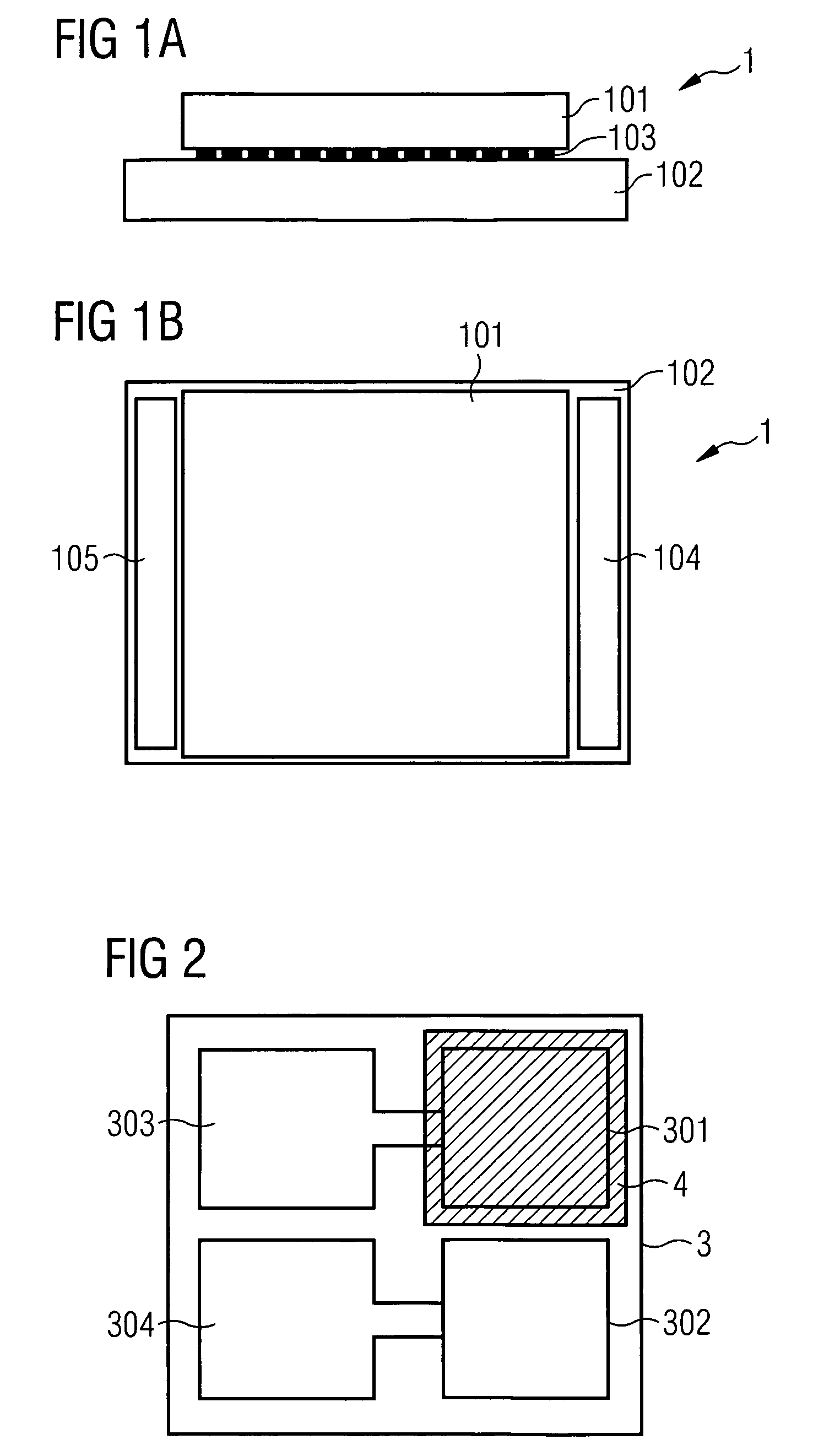
[0029]FIGS. 1A and 1B show an exemplary embodiment of a micro-Peltier chip 1 with an edge length of preferably less than 5 mm. In particular, the micro-Peltier element illustrated preferably has a size of approximately 1.3×1.3×0.3 mm3 (length×width×height).

[0030]The micro-Peltier chip 1 has an upper rectangular semiconductor substrate 101 and a lower rectangular semiconductor substrate 102 that are electrically interconnected via a contacting layer 103. Two metalizations 104, 105 serving as contacts permit a voltage to be applied to the micro-Peltier chip 1. Peltier coolers utilize the Peltier effect, in accordance with which heat is extracted from or fed to the interface between two different conductors when current is flowing, depending on the direction of the current. As is known per se to the person skilled in the art, the micro-Peltier chip 1 is cooled or heated depending on the voltage applied, and so this will not be examined further.

[0031]In the present case, the micro-Pelti...


PUM


Abstract

The invention relates to an optoelectronic arrangement having a laser component. There are provided: a cooling device of small design for cooling the laser component down to a constant temperature, a device for the direct optical detection of the emitted wavelength of the laser component, whose signal is used to control the cooling device, and a package of small design with an extent of at most 6.5 mm perpendicular to the optical axis of the laser component and in which the above named components are arranged. The invention also relates to a method for controlling the emitted wavelength of a laser component.

Description

REFERENCE TO RELATED APPLICATIONS[0001]This application is related to U.S. application Ser. No. 10 / 742,534 filed on Dec. 19, 2003, entitled “Optoelectronic Arrangement Having at Least One Laser Component, and a Method for Operating a Laser Component”.FIELD OF THE INVENTION[0002]The invention relates to an optoelectronic arrangement having a laser component, and to a method for controlling the emitted wavelength of a laser component. It enables the exact setting and monitoring of the emitted wavelength of a laser component.BACKGROUND OF THE INVENTION[0003]For the purpose of transmitting as large a quantity of data as possible via an optical waveguide, it is known in optical telecommunications to multiplex the data to be transmitted. One possibility for this purpose is to transmit information independently and simultaneously over one waveguide with the aid of several wavelengths (wavelength division multiplexing—WDM). It is necessary in this case to keep reliably on the transmission s...

Claims


Application Information

Patent Timeline
Patent Type & Authority Patents(United States)
IPC IPC(8): G02B6/36G02B6/00G02B6/42
CPCG02B6/4201
Inventor KROPP, JORG-REINHARDTWEIGERT, MARTIN
Owner INFINEON TECH AG
Learn More