Vice for tying a hook for fly-fishing

a hook and hook clip technology, applied in fishing, workpiece holders, manufacturing tools, etc., can solve the problems of not being held, damaged or broken, inconvenient and practical defects,

Inactive Publication Date: 2007-06-19
YONENOI KIMIO
View PDF3 Cites 10 Cited by
  • Summary
  • Abstract
  • Description
  • Claims
  • Application Information

AI Technical Summary

Benefits of technology

[0011]In a further another embodiment of the present invention a vice for fly tying comprises a pin hole prepared at an extreme portion of the revolving base so that centering of the fly hook can be easily done and exactly to make a fly.

Problems solved by technology

In this fly tying, generally the vice showed reasonable function, however, it has inconveniences and practical defects as follows.
Firstly, all fly hooks, which is respectively of different sizes and different forms, can not be held exactly with the vice, due to limitation of their width and length, even though differential sized multiple grooves are provided with either a pair of relative holding surfaces of the vice.
If those hooks are held with the vice without any considerations, they may be damaged or broken away because unreasonable relations appear forcibly between the hooks and grooves respectively.
Accordingly, it is very difficult to hold the fly hook at the proper position and in the proper direction, even if by the expert, to say nothing of the beginner, without a careful operation.
The vice can not also be regarded as a functional tying device because it can not execute a detailed fly tying operation, due to lack of a centering means for holding temporarily the hook and fixedly in the jaw.

Method used


Image

  • Vice for tying a hook for fly-fishing
  • Vice for tying a hook for fly-fishing
  • Vice for tying a hook for fly-fishing

Examples


Embodiment Construction

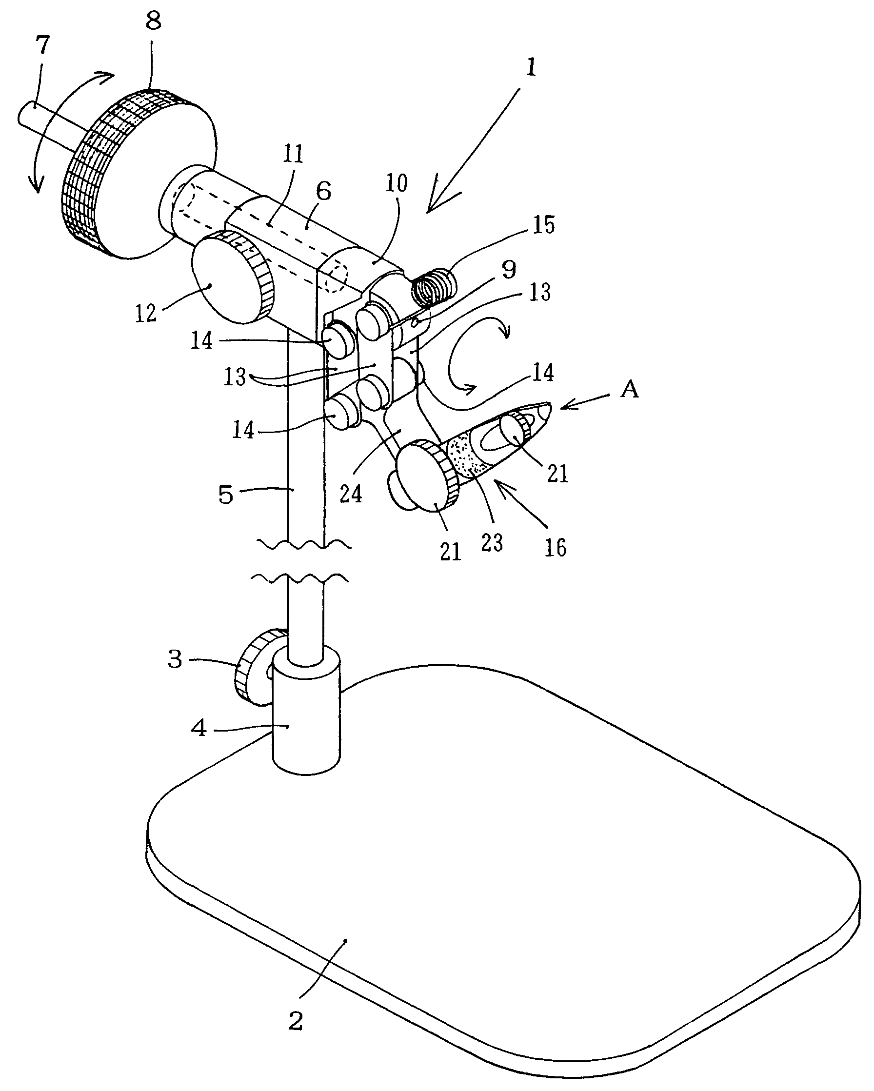
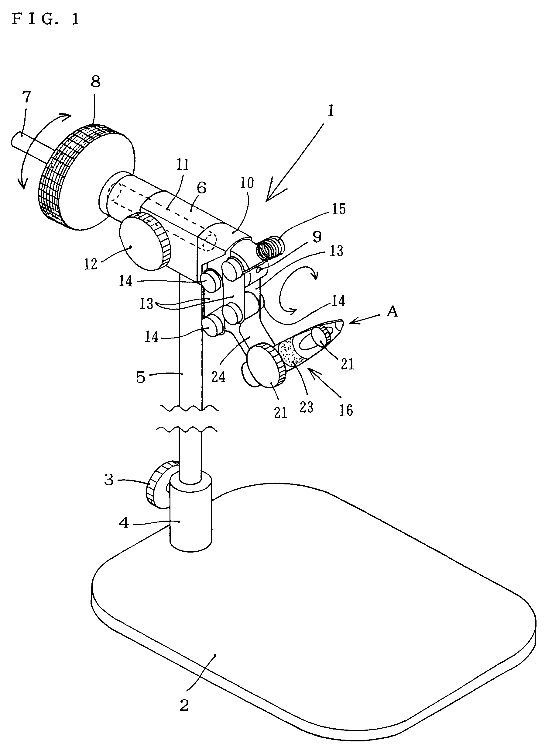
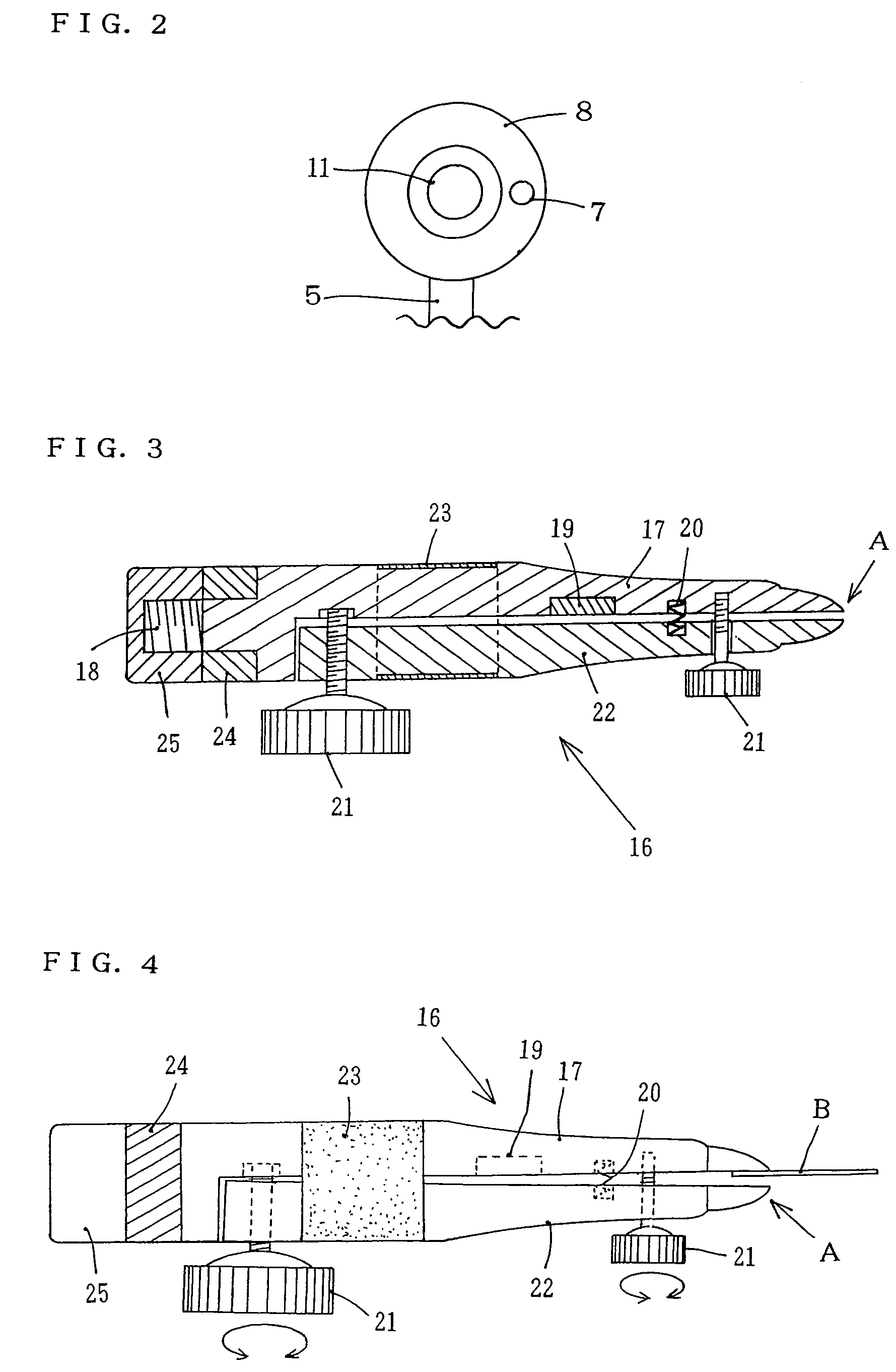
[0021]A tying vice 1 for the present invention, as shown FIG. 1, comprises a base 2 having a suitable area and weight; an axle tube 4 attached at a rear end of the base and provided with a tightening screw 3; a maintaining base 6 having a through hole therein and set at an upper end portion of a support 5 connected adjustably into the axle tube 4; a revolving knob 8 having a secondary knob 7 fixedly connected with the maintaining base 6 in its hole by an axle bar 11 and an adjustable screw 12; a revolving base 10 set at a front end of the maintaining base 6 through the axle bar 11 and providing a pin hole 9 on its front extreme portion; and a movable holding member 16 connected with the revolving base 10 through two pairs of movable connecting plates 13 and a connecting axle bar 24 to revolve about an arrow f.

[0022]The movable connecting plates 13 are also attached pivotally to both sides of the revolving base 10 by upper screw set 14 at their one end portion, with a holding coil 15...


PUM


Abstract

A vice for fly tying comprises a support disposed adjustably on a suitable base plate, a maintaining base attached on the support and provided with a fastening screw on its side surface, a revolving knob connected with the maintaining base at its rear end, a revolving base rotatively connected with the maintaining base at its rear end, through a through hole of the later by an axle bar of the revolving knob, and a holding member pivotally connected with the revolving base, through two pairs of movable connecting plates attached to both sides of the later and a connecting axle bar attached on its rear end portion. The holding member comprises an axial holding piece made of a magnetic inductive material and a movable holding piece, and is provided with a pair of adjusting screws at its rear portion and front portion, a magnet on an inner surface of the former piece, a spring held between the both inner surfaces of both pieces and a rubber ring wound centrally on both pieces, so that the fly hook can be exactly held between the both pieces of the jaw portion for fly tying.

Description

BACKGROUND OF THE INVENTION[0001]This invention relates to a vice for tying a hook, particularly a fly used in fishing. More particularly the invention relates to a vice for tying a fly for fly-fishing, which can be easily centered on a hook in a manufacturing process of the fly, by inducing a magnetic field on an end portion of the vice, a so-called jaw portion, to set magnetically the fly hook into the jaw.[0002]Customarily, a fly for fly fishing is manufactured by holding on a tying vice firstly the fly hook and thereafter, tying on the fly hook a material such as a bird feather or animal hair together with a thread, to make a suspected bait, which is alike to an aquatic insect.[0003]In such manufacture of the fly, various vices have been proposed, such as in Published Japanese Patent Application Kokai 2001-112394. The vice is provided with a jaw on its extreme end portion which comprises a pair of holding portions, having double joint surfaces and differently sized multiple groo...

Claims


Application Information

Patent Timeline
Patent Type & Authority Patents(United States)
IPC IPC(8): B25B1/22
CPCA01K97/28Y10S269/907
Inventor YONENOI, KIMIO
Owner YONENOI KIMIO
Why Eureka
Try Eureka