
Accelerometer based tilt sensor and method for using same

a technology of accelerometer and tilt sensor, which is applied in the direction of instruments, digital computer details, devices characerised by mechanical means, etc., can solve the problems of difficulty in determining whether the device is functioning properly, accelerometer cannot react to inclination at the same time, and it is difficult to precisely align the coordinate system of the accelerometer with the coordinate system of the desired measuremen

Active Publication Date: 2007-06-19
DANFOSS POWER SOLUTIONS INC
View PDF7 Cites 27 Cited by
  • Summary
  • Abstract
  • Description
  • Claims
  • Application Information

AI Technical Summary

Benefits of technology

The patent describes a tilt sensor that has three accelerometers mounted on a base in a common plane. These accelerometers are evenly spaced and positioned at approximately 120 degrees to each other. The first accelerometer is also positioned at a 45 degree angle with respect to one of the axes of the common plane. The patent also provides a method for using the tilt sensor to determine the angle of inclination based on the accelerometer readings. The technical effect of this invention is to provide a more accurate and reliable tilt sensor for various applications such as navigation and sports equipment.

Problems solved by technology

One disadvantage with conventional accelerometer based tilt sensors is that it is often difficult to determine whether the device is functioning properly.
The weakness with these self test modes is that the accelerometer cannot react to inclination at the same time that it is in the test mode.
Another disadvantage of conventional tilt sensors is that, during installation, it often is difficult to precisely align the coordinate system of the accelerometers with the coordinate system of the desired measurements.
Often such precision requires complicated manufacturing processes.
However, it is difficult to maintain the same level of precision between the accelerometer and the mounting points of the final product.
Still another disadvantage of conventional tilt sensors is that it is difficult if not impossible to change the coordinate system of the final assembled product without changing the physical design so that it can be used in various applications with differing coordinate systems.

Method used


Image

  • Accelerometer based tilt sensor and method for using same
  • Accelerometer based tilt sensor and method for using same

Examples


Embodiment Construction

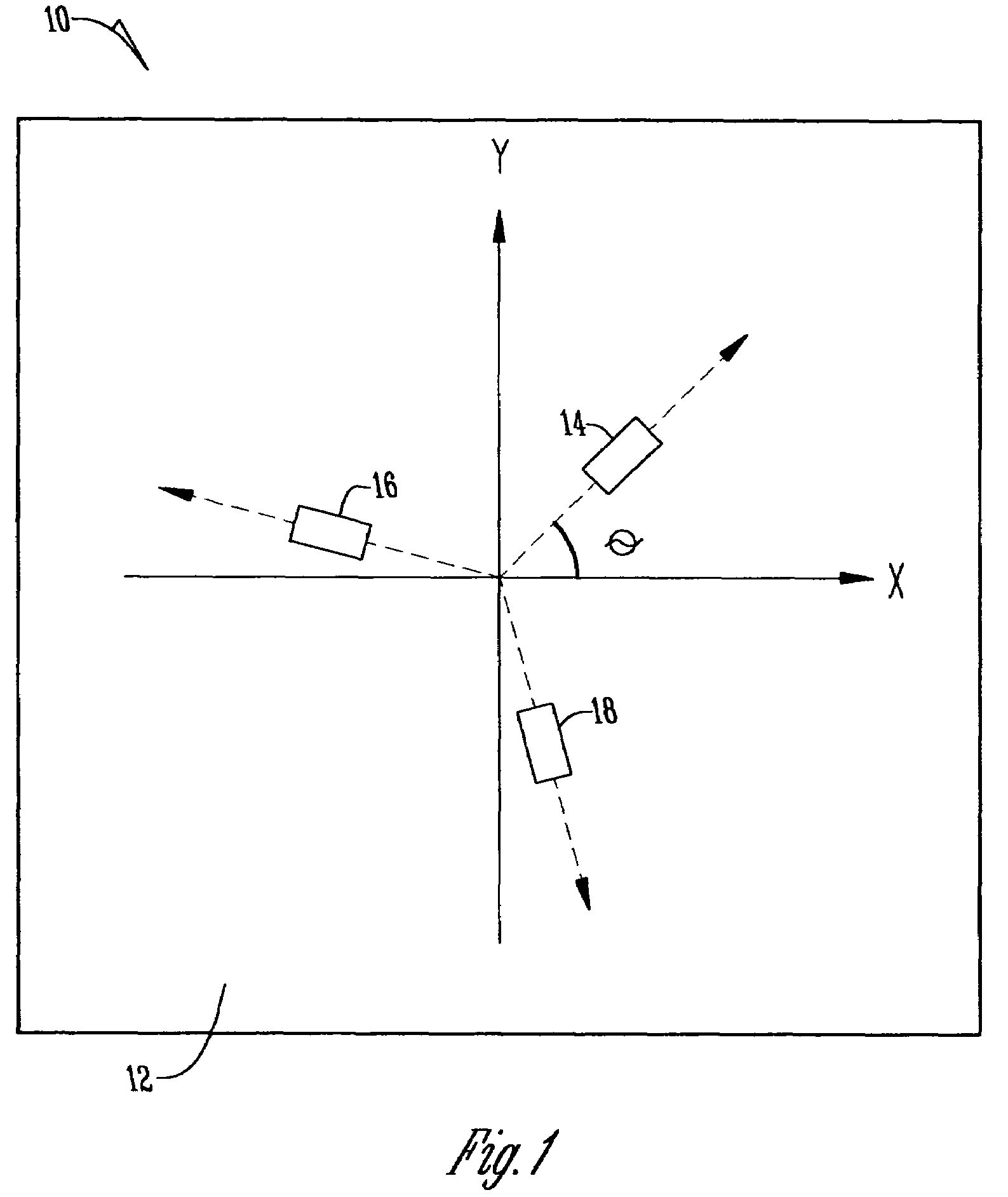
[0013]With respect to FIG. 1, a tilt sensor 10 is provided having a base 12 for fixation to a final assembled product, such as heavy machinery or, in a simplified application, a carpenter's level. The base 12 may include a housing (not shown) and is made of any conventional material known in the art.

[0014]At least three accelerometers 14, 16, and 18 are mounted to the base 12, as shown in FIG. 1. The present invention contemplates that additional accelerometers may be used for redundancy or to sense tilt in more than two directions. Additionally, accelerometers 14-18 include any type of force-based accelerometer that sense deviations in the force of gravity with the degree of tilt.

[0015]The accelerometers 14-18 are positioned in a common plane, such as an X-Y plane. While the X and Y axes typically are associated with those axes parallel to the horizontal, any orientation of the axes is contemplated by the present invention, including a Z or vertical axis. Preferably, the accelerome...


PUM


Abstract

A tilt sensor and a method for the use of the tilt sensor to calculate the degree of tilt, whereby the tilt sensor has at least three accelerometers mounted to a base, the accelerometers are positioned in a common plane, and wherein each is preferably at an equally spaced angle from one another.

Description

BACKGROUND OF THE INVENTION[0001]The present invention relates to inclinometers or tilt sensors and, more specifically, an accelerometer based tilt sensor and method for using the same.[0002]Accelerometers are often mounted to various devices and are used to measure the degree of tilt of the device with respect to a horizontal axis. Accelerometers act under the acceleration of gravity and sense deviations in the gravitational field. Specifically, as an accelerometer is tilted at an angle with respect to the horizontal, the vertical component of the force of gravity acting on the accelerometer changes, causing the electronic components within the accelerometer to react differently, and varying the output reading of the accelerometer. Some accelerometers utilize a piezoelectric crystal and a mass whereby the changing angle of inclination causes the mass to apply varying pressure on the piezoelectric crystal, which produces the output signal. In other accelerometers, a capacitor and re...

Claims


Application Information

Patent Timeline
Patent Type & Authority Patents(United States)
IPC IPC(8): G01P3/04
CPCG01B21/22G01C9/02
Inventor DAVIDSON, LINCOLN
Owner DANFOSS POWER SOLUTIONS INC
Learn More