Image forming apparatus with a removable process unit capable of securing rotation transmission accuracy without stressing a holding portion despite shaft misalignment
a technology of rotating transmission accuracy and process unit, which is applied in the field of image forming apparatus, can solve the problems of difficult attachment/removal of image forming unit, apparatus itself being larger, and affecting the accuracy of rotation transmission, so as to achieve high strength, secure rotation transmission accuracy, and secure the effect of rotation transmission accuracy
- Summary
- Abstract
- Description
- Claims
- Application Information
AI Technical Summary
Benefits of technology
Problems solved by technology
Method used
Image
Examples
first embodiment
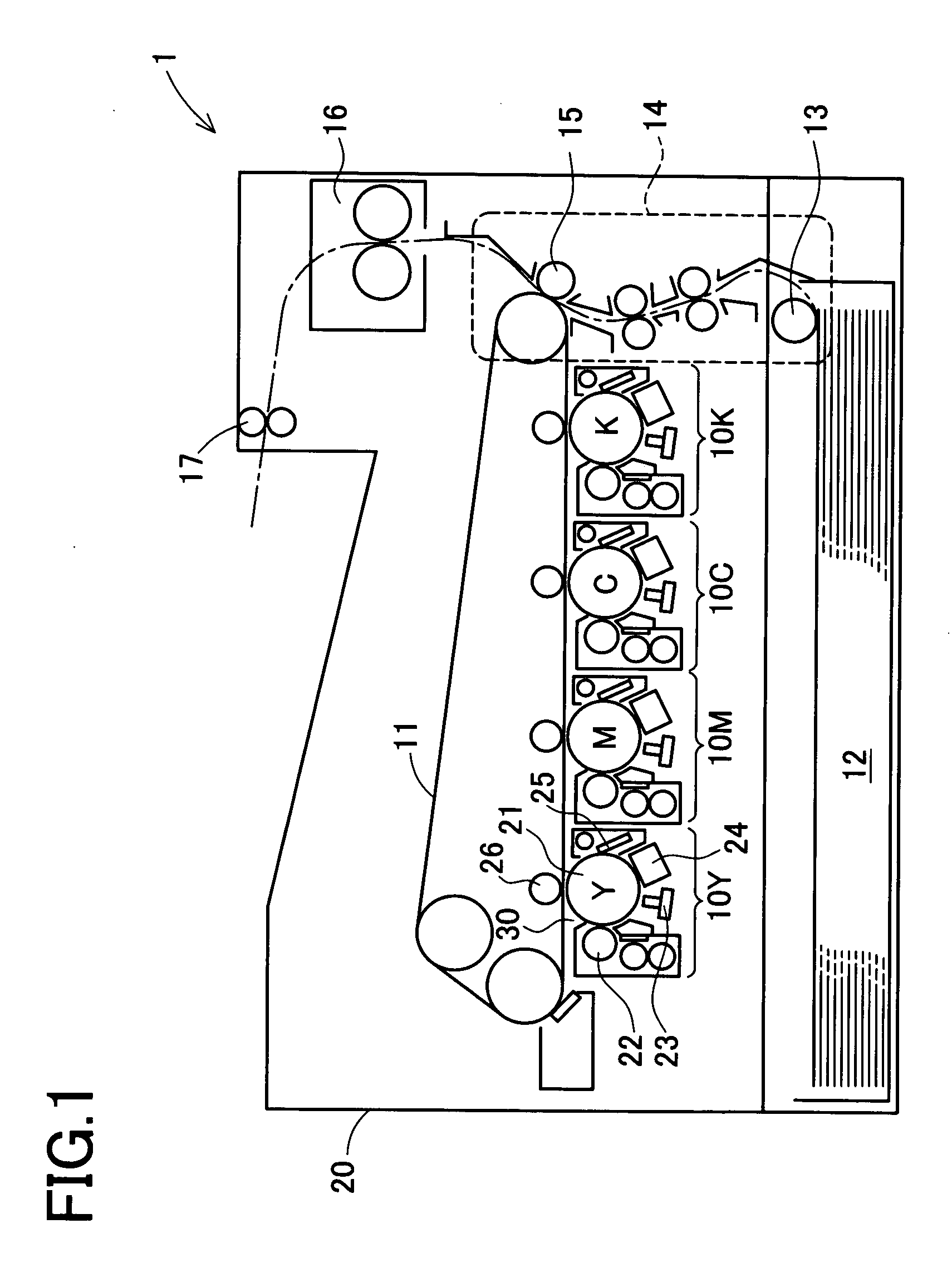
[0045]There will be described a first embodiment in detail by referring to drawings. In this embodiment, the present invention is applied to a tandem type color printer.
[0046]In a color printer 1 directed to this embodiment, as shown in FIG. 1, image forming sections of respective colors 10Y, 10M, 10C, and 10K are arranged along an intermediate image transfer belt 11. At the bottom portion of the color printer, there is attached a paper cassette 12. Sheets of paper in there are fed to a paper carrying section 14 by a paper feeding roller 13. An image formed on the intermediate image transfer belt 11 by superimposing respective color images through the image forming sections 10Y, 10M, 10C, and 10K is transferred onto a sheet of paper at a secondary image transfer section 15, and fixed at an image fixing section 16. A sheet of paper on which an image is thus formed is ejected by a paper ejecting roller 17. All of the above-mentioned structure is housed in a cover box 20.
[0047]Each of ...
second embodiment
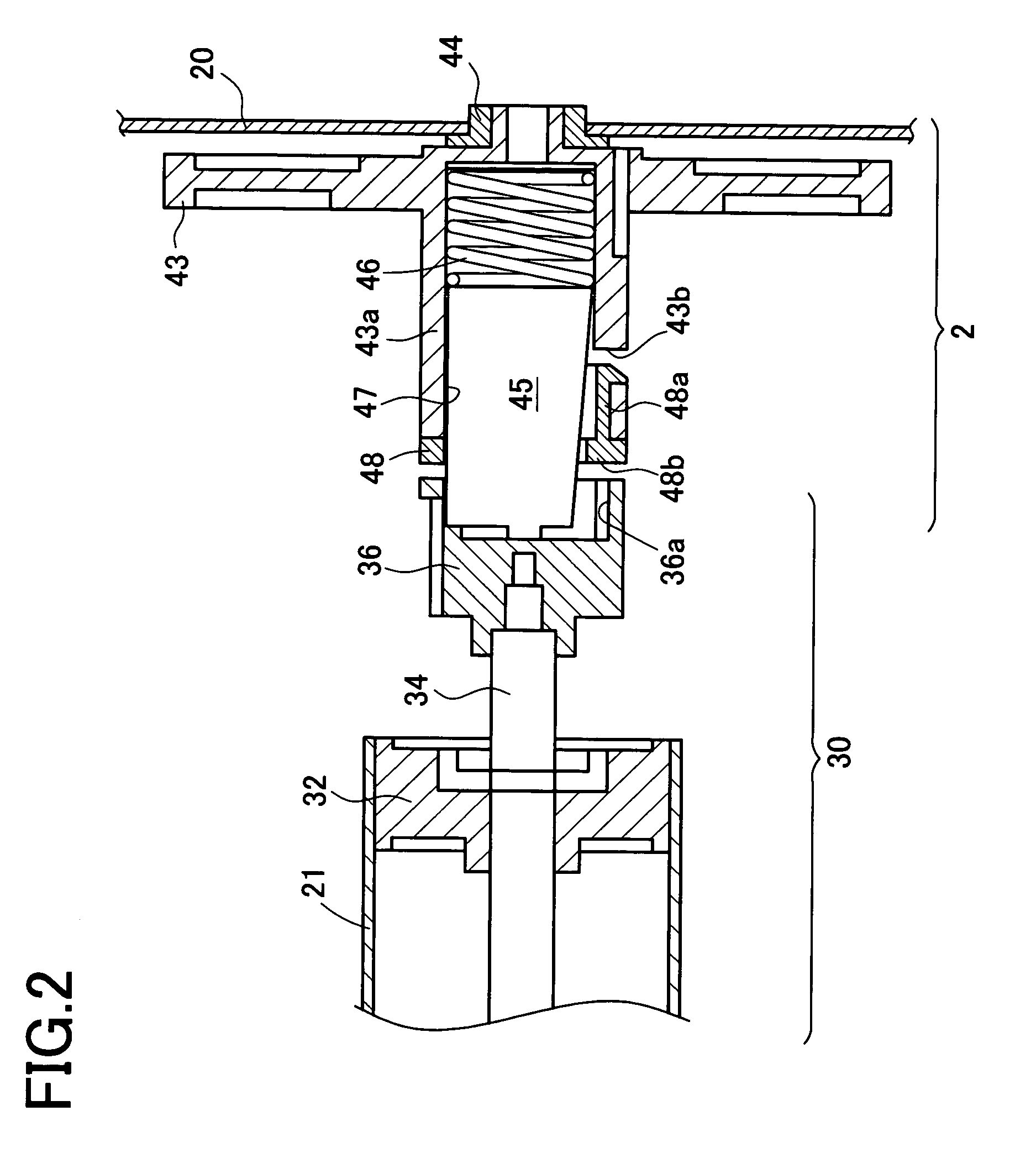
[0072]Hereinafter, the second embodiment of the present invention will be described in detail with reference to the accompanying drawings. This embodiment also concerns an application of the present invention to the tandem type color printer. The entire configuration of this embodiment is the same as FIG. 1 of the first embodiment.
[0073]Next, FIGS. 11, 12 show an outline of the connecting portion of the main body 2 and image forming unit 30 of this embodiment. This connecting portion is disposed on a deeper side in FIG. 1 of the color printer. FIG. 11 shows a sectional view of this connecting portion. FIG. 12 is an exploded oblique perspective view of the right half of FIG. 11. In the image forming unit 30, as shown on the left side of FIG. 11, a flange 32 is fixed to an end portion of a photosensitive body 21 and the rotation shaft 34 of the photosensitive body 21 is fixed onto the flange 32.
[0074]On the side of the main body 2, as shown on the right side of FIG. 11, a gear 43 is f...
third embodiment
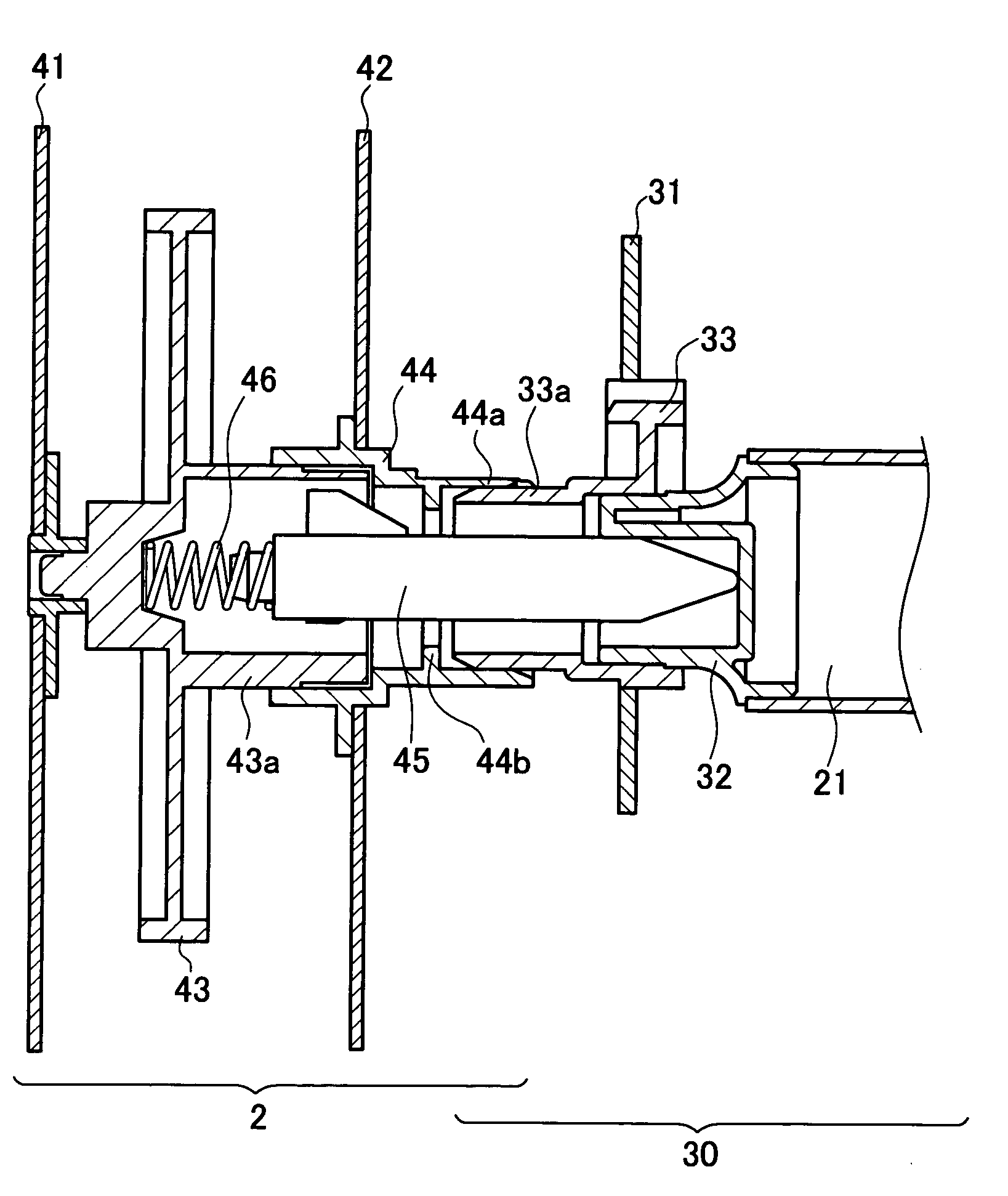
[0091]Hereinafter the third embodiment of the present invention will be described in detail with reference to the accompanying drawings. This embodiment is different from the first embodiment in only the connecting portion between the image forming unit 30 and the main body 2. Because the entire structure thereof is substantially equal, only different points will be described here.
[0092]FIG. 17 shows the schematic structure of the connecting portion of this embodiment. In this Figure, the image forming unit 30 is represented on the right side thereof. The image forming unit 30 is held by the housing 31 and it includes a photosensitive body 21, a flange 32 and a shaft holder 33. The flange 32 is fixed to an end portion of the photosensitive body 21 and rotated integrally with the photosensitive body 21. The shaft holder 33 supports an end portion of the flange 32 rotatably and is fixed to the housing 31. A cylindrical fixing section 33a is formed at a left end portion in the Figure o...
PUM
 Abstract
Description
Claims
Application Information
 - Generate Ideas
- Intellectual Property
- Life Sciences
- Materials
- Tech Scout
- Unparalleled Data Quality
- Higher Quality Content
- 60% Fewer Hallucinations
Browse by: Latest US Patents, China's latest patents, Technical Efficacy Thesaurus, Application Domain, Technology Topic, Popular Technical Reports.
© 2025 PatSnap. All rights reserved.Legal|Privacy policy|Modern Slavery Act Transparency Statement|Sitemap|About US| Contact US: help@patsnap.com


