Display apparatus for visually communicating information pertaining to a worker's whereabouts
a technology of visual communication and display apparatus, which is applied in the direction of identification means, display means, show cards, etc., can solve the problems of inability to efficiently determine the whereabouts of co-workers, time-consuming and generally inefficient approaches, and employers are unable to provide such equipment to workers
- Summary
- Abstract
- Description
- Claims
- Application Information
AI Technical Summary
Benefits of technology
Problems solved by technology
Method used
Image
Examples
first embodiment
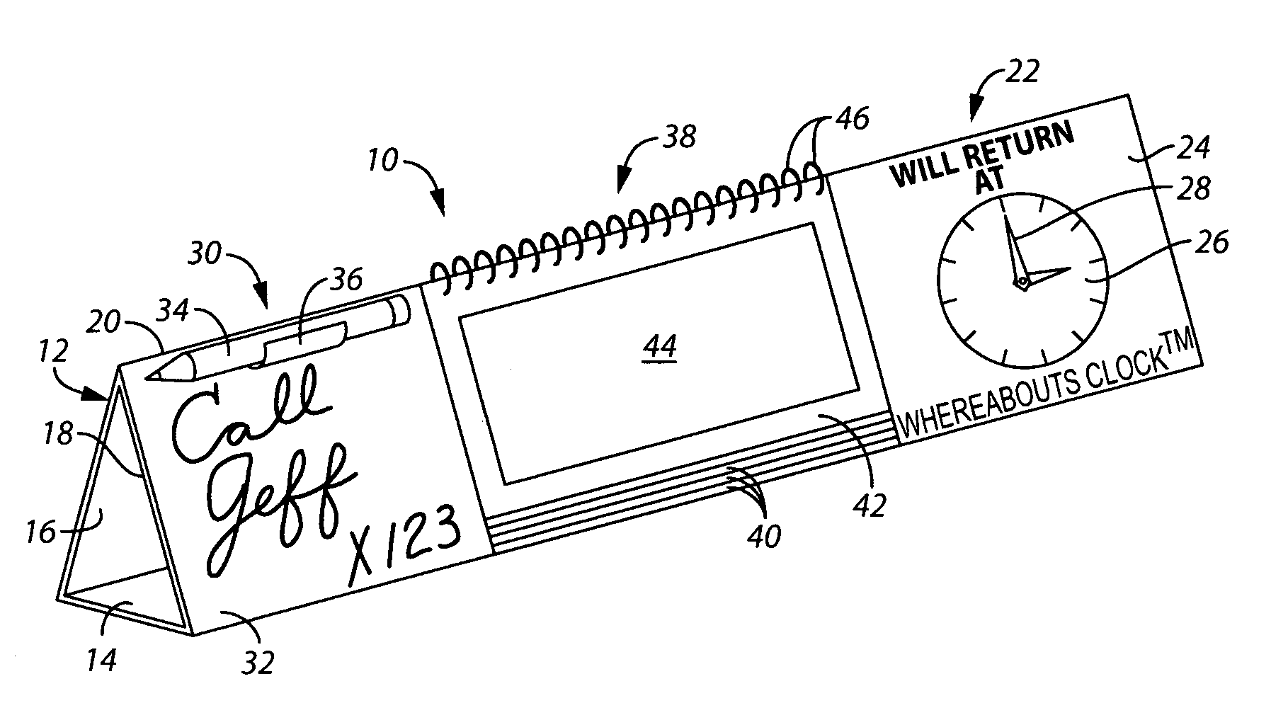
[0039]Referring initially to FIG. 1, in the invention a visual display apparatus, shown generally as reference numeral 10, is particularly configured for being supported upon a desktop or similar furniture support surface (not shown) within an office or other workspace. The apparatus has a horizontally elongated triangular main body 12 including a base panel 14, a rear panel 16 and a front panel 18. The rear panel 16 and front panel 18 meet at a common upper edge, or apex 20.
[0040]A right portion 22 of the main body 12 includes an outer surface 24 having a clock face 26 disposed thereon. Preferably, the clock face 26 is either directly printed on surface 24 or, alternatively, comprises a preprinted adhesive label. A pair of manually adjustable clock hands 28 are provided and can be set by a worker to indicate an estimated time of return to the work space.
[0041]A left portion 30 of the main body 12 includes an erasable marking surface 32, as is well known in the art, for enabling inf...
second embodiment
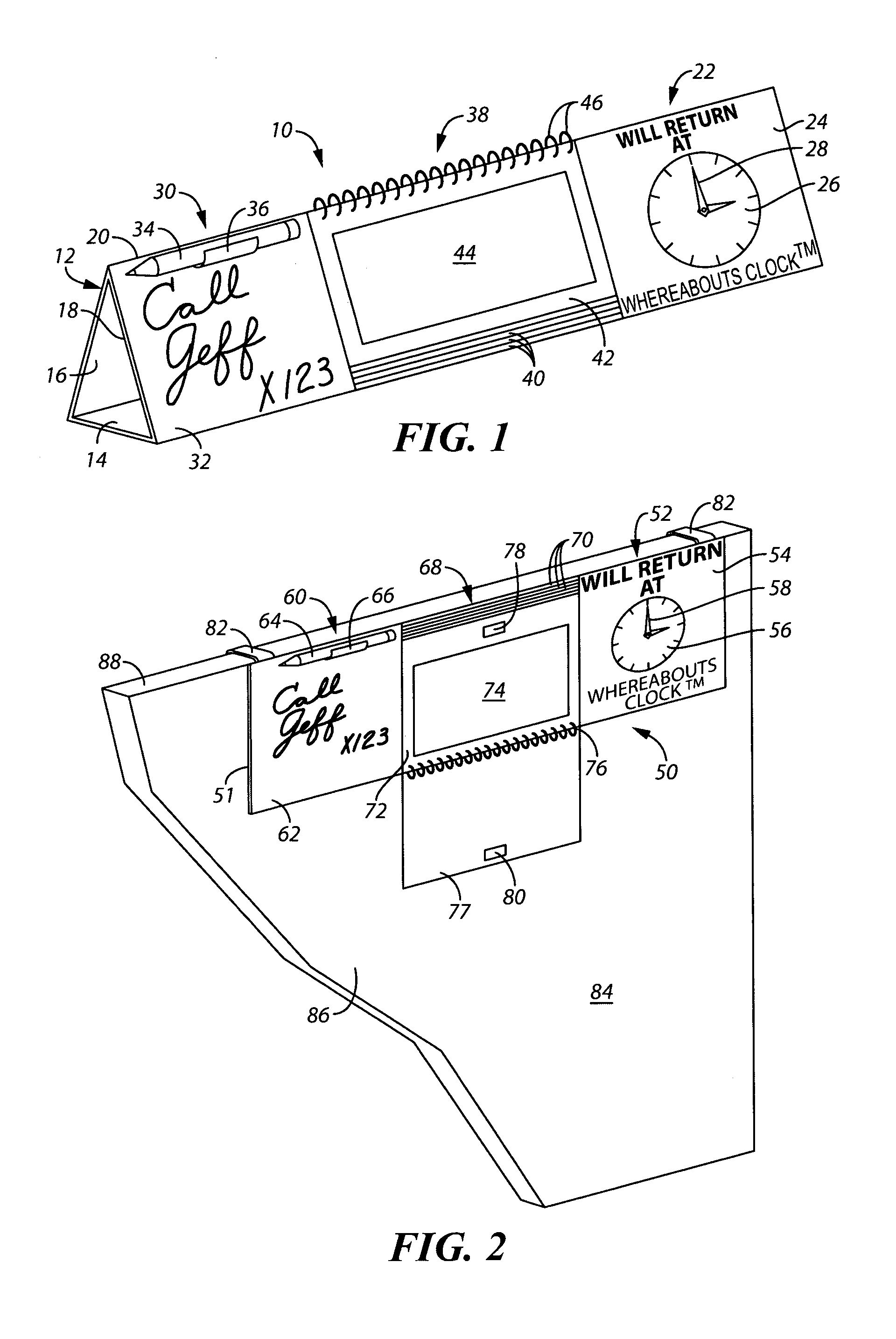
[0043]Referring now to FIG. 2, in the invention a visual display apparatus, shown generally as reference numeral 50, is particularly configured for being hung from an upper edge 88 of an office partition wall 84, such as a conventional cubicle wall, such that the apparatus is maintained substantially flush with a main partition wall surface 86. The apparatus has a generally planar horizontally elongated rectangular main body 51 and includes a right portion 52, a left portion 60 and a middle portion 68, generally corresponding to the right portion 22, left portion 30 and middle portion 38 of the display apparatus described heretofore with respect to FIG. 1.
[0044]Right portion 52 of main body 51 includes an outer surface 54 having a clock face 56 disposed thereon, and a pair of manually adjustable clock hands 58 as previously described with respect to FIG. 1. Likewise, left portion 60 of main body 51 includes an erasable marking surface 62, and an erasable marker 64 secured within a c...
third embodiment
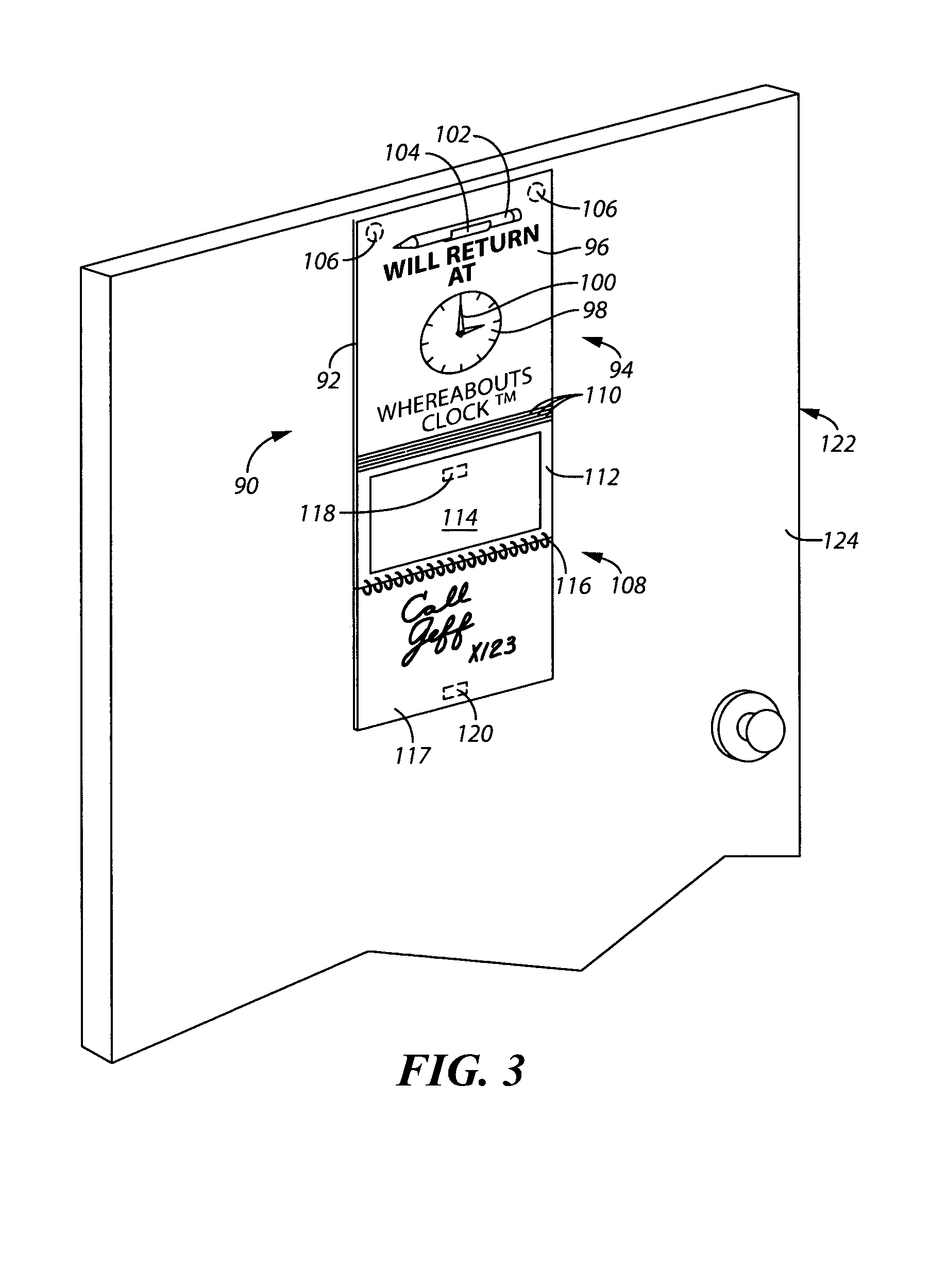
[0047]Referring now to FIG. 3, in the invention a visual display apparatus, shown generally as reference numeral 90, is particularly configured for being directly secured to the surface of a vertical office structure. In FIG. 3, and the accompanying description, the apparatus is described with respect to a door panel 122 for convenience. However, as will be apparent to those skilled in the art, the apparatus is adapted for attachment to any vertical structure surface including, for example, an office window or wall.
[0048]The apparatus 90 includes has a generally planar vertically elongated rectangular main body 92 and includes an upper portion 94 and a lower portion 108. Upper portion 94 of main body 92 includes an outer surface 96 having a clock face 98 disposed thereon, and a pair of manually adjustable clock hands 100 as previously described with respect to FIGS. 1 and 2.
[0049]Lower portion 108 includes a plurality of informational cards 110 carried by a horizontally disposed spi...
PUM
 Abstract
Description
Claims
Application Information
 - R&D
- Intellectual Property
- Life Sciences
- Materials
- Tech Scout
- Unparalleled Data Quality
- Higher Quality Content
- 60% Fewer Hallucinations
Browse by: Latest US Patents, China's latest patents, Technical Efficacy Thesaurus, Application Domain, Technology Topic, Popular Technical Reports.
© 2025 PatSnap. All rights reserved.Legal|Privacy policy|Modern Slavery Act Transparency Statement|Sitemap|About US| Contact US: help@patsnap.com


