
Portable electronic equipment having a photographic function and a concealable lens

a technology of electronic equipment and function, applied in the field of portable electronic equipment having a photographing function, can solve the problems of inability to ensure the photographing of a desired image, difficulty in accurately checking the photographing range, and inability to achieve the desired image, so as to prevent the failure of photographing, the effect of smooth decision of composition

Inactive Publication Date: 2007-05-29
NEC CORP
View PDF23 Cites 10 Cited by
  • Summary
  • Abstract
  • Description
  • Claims
  • Application Information

AI Technical Summary

Benefits of technology

The present invention provides a portable electronic equipment that allows a photographer to know the position of an object and the range of a scene during photographing. It also allows for smooth decision-making and prevents photographing failures without compromising the privacy of the photographer. The equipment includes a forming means for creating an image of an object, a concealing means for blocking the image, and a judging means for determining when a predetermined condition is met. The equipment can be a cellular phone with a camera lens and a lens concealing plate that can be controlled to transmit or block light. The equipment also includes a decision circuit for deciding the composition of the object and a display for displaying characters or images.

Problems solved by technology

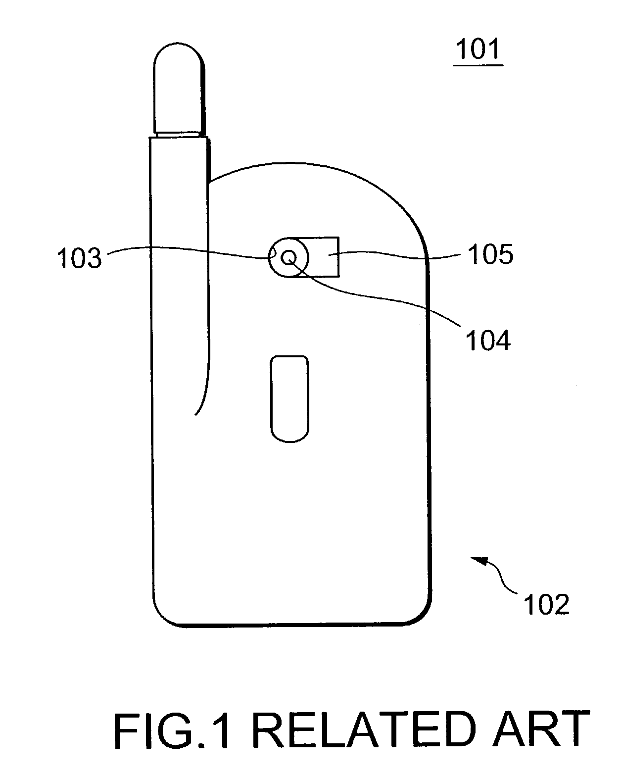
However, visibility of the camera lens 104 causes a problem that when the operator performs an operation in a place of many people (in a train, a store or the like), the people around him may feel uneasy or uncomfortable because of possible impingement on rights of portrait by being photographed without notice or awareness.
For reasons of design, the mirror surface unit 104 is provided only in a small region so as not to stand out, making it difficult to accurately check the photographing range.
Consequently, impossibility of assuring photographing of a desired image has been a problem.

Method used


Image

  • Portable electronic equipment having a photographic function and a concealable lens
  • Portable electronic equipment having a photographic function and a concealable lens
  • Portable electronic equipment having a photographic function and a concealable lens

Examples


Embodiment Construction

[0039]Hereinafter, each embodiment of the present invention will be described in detail with reference to the drawings.

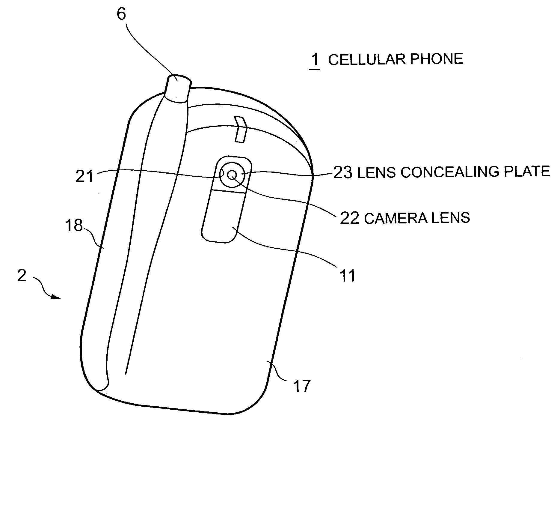
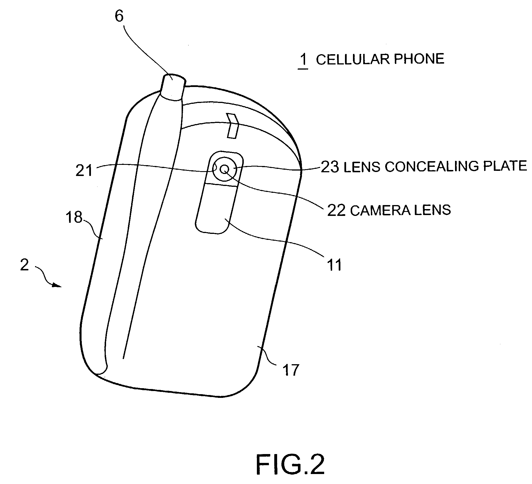
[0040]FIG. 2 is a perspective view of a folded cellular phone according to a first embodiment of the present invention, showing a closed state of a casing of the cellular phone. FIGS. 3A and 3B are perspective views of the cellular phone, showing an opened state of the casing of the cellular phone. As shown in FIGS. 2, 3A and 3B, the casing 2 comprises upper and lower casings 17 and 18 connected to each other at a hinge unit 16. The hinge unit 16 provides a foldable structure to the cellular phone 1 by rotatably connecting the upper and lower casings 17 and 18 to each other. And also, the cellular phone 1 of the embodiment comprises a photographing function with an incorporated electronic camera and a data communication function connected to, for example, the Internet to enable access to be made to homepages and electronic mail to be transferred in addition to an or...


PUM

PropertyMeasurementUnit
diameteraaaaaaaaaa
light transmittanceaaaaaaaaaa
timeaaaaaaaaaa

Abstract

When no photographing is carried out, a control unit applies no voltage to a dimming film of a lens concealing plate, sets a light blocking state to scatter incident light, and prevents a camera lens from becoming visible. When an operator depresses a photographing mode selection key, the control unit applies a predetermined voltage to the dimming film to set a transparent state, thereby enabling photographing to be carried out. In this state, when photographing a landscape, the operator directs the camera lens to an object, sets a cellular phone ready, decides a composition by watching an image of the object displayed on a main display unit, and correcting a position of the cellular phone, and depresses the photographing mode key again.

Description

BACKGROUND OF THE INVENTION[0001]1. Field of the Invention[0002]The present invention relates to a portable electronic equipment having a photographing function, and more particularly, it relates to a portable electronic equipment such as a cellular phone comprising an electronic camera that is used for photographing landscapes or people.[0003]2. Description of the Related Art[0004]In recent years, a portable electronic equipment such as a cellular phone has been provided with not only calling functions but also a data communication functions. Browsers and mailer programs have been loaded to enable access to be made to home pages through Internet, and electronic mail to be transferred. Thus, Internet connection services and electronic mail services can be easily enjoyed irrespective of time and place.[0005]Recently, for example as disclosed in Japanese Patent Application Laid-Open No. 2001-245267, a portable electronic equipment loaded with an electronic camera has been popularized....

Claims


Application Information

Patent Timeline
Patent Type & Authority Patents(United States)
IPC IPC(8): G02B13/16H04N5/225G02F1/13G02F1/1334G02F1/1335G02F1/13357G02F1/1347G03B17/56H04M1/00H04M1/02H04M1/21H04M1/72403H04M1/7243H04M1/72445H04N5/232
CPCH04M1/0214H04M1/0245H04M1/72522H04N5/23293H04M1/72547H04M1/72561H04M2250/16H04M2250/52H04M1/7243H04M1/72403H04M1/72445H04N23/633
Inventor SHIMAMURA, MASAKI
Owner NEC CORP
Learn More