Liquid discharge device and liquid discharge method

Inactive Publication Date: 2007-05-29
SONY CORP
View PDF10 Cites 8 Cited by
  • Summary
  • Abstract
  • Description
  • Claims
  • Application Information

AI Technical Summary

Benefits of technology

[0029]Accordingly, it is an object of the present invention to provide a liquid discharge device having the advantage of reduction of positional irregularities in dot columns, and in particular, with the serial-method arrangement, to provide a liquid discharge device having the advantage of preventing occurrence of streaks between dot columns due to irregularities in an array of discharge portions, using the technique for performing liquid-droplet discharge with deviation, which has been proposed by the present inventors (e.g., Japanese Unexamined Patent Application Publication No. 2002-320861, Japanese Unexamined Patent Application Publication No. 2002-320862, and Japanese Unexamined Patent Application Publication No. 2003-37343, which are undisclosed techniques, have relation to the present invention, and are not conventional techniques), which will be referred to as “first object” hereafter.
[0030]Furthermore, it is an object thereof to provide a liquid discharge device having the advantage of the fact that even in the event that malfunctioning such as non-discharge or the like occurs in a part of the liquid discharge portions, occurrence of streaks or the like is prevented, as well as the positional irregularities in landing positions of liquid droplets becoming less conspicuous, which will be referred to as “second object” hereafter.
[0036]Thus, the liquid droplet lands at the pixel region such that at least a part of the landing liquid droplet region is included within the pixel region, with random deviation as to the pixel region. This reduces the maldistribution of the landing positions of liquid droplets due to irregularities in the properties of the liquid discharge portions or the like, whereby overall arrays thereof follow a uniform and isotropic distribution.
[0042]Thus, the liquid droplet lands at the pixel region such that at least a part of the landing liquid droplet region is included within the pixel region, with positional irregularities within the pixel region. This reduces the maldistribution of the landing positions of liquid droplets due to irregularities in the properties of the liquid discharge portions or the like, whereby overall dot columns follow a uniform and isotropic distribution.

Problems solved by technology

On the other hand, with the ink jet printers, liquid droplets are discharged with some irregularity due to the configuration thereof.
However, directional irregularities due to positioning of the liquid discharge portions (head) are markedly conspicuous, even in the event the amount of the irregularities is minute.
In the event that a dot array is printed with the directional irregularities of around 20% or more, the irregularities are markedly conspicuous, and in general, such irregularities are recognized as being defective.
In this case, following the first printing, undesirable unprinted gaps occur.
However, in actual practice, it is almost impossible to manufacture a head having such a configuration due to various kinds of problems, such as manufacturing method, a small yielding percentage, overheating, costs, and the like.
Note that manufacturing of the aforementioned head chip also has various kinds of limitations, and the length thereof in the direction of the liquid discharge portion array is limited to 1 inch or shorter at the most, which is a practical limit.
However, the above-described conventional methods have problems as follows.
First, the first method for the serial method (the technique wherein the dot size is increased) has an advantage with regard to irregularities in dot positions, but leads to a problem of conspicuous dot roughness due to an increase of the dot size.
Accordingly, with printing images requiring intermediate tones, such as photographs, a problem occurs in that the sensation of image roughness increases.
However, there is the need to form a great number of dots in both the main scanning direction and the sub-scanning direction, leading to a problem of low recording speed.
In order to solve this problem, a great number of the liquid discharge portions must be moved at a speed as high as possible, often leading to a problem of reduction of reliability and a problem of high costs.
On the other hand, while an arrangement employing the line method may employ the above-described first method wherein large-sized dots are employed so as to reduce the influence of irregularities in discharge from the liquid discharge portions, the same problem occurs as with the aforementioned serial method arrangement employing the first method.
Furthermore, with the line method arrangement, multiple head chips are connected one to another, often leading to a problem of a margin of error in the array intervals.
Furthermore, there is a problem in that the thickness and the like of these multiple head chips is not always uniform.
However, it is difficult to move the head only in the horizontal direction (the direction of the width of the recording medium, i.e., the direction vertical to the main scanning direction of the line method arrangement).
Furthermore, unlike the sublimation printer, the ink jet printer requires some period of time for drying the dots arrayed on the recording medium (ink dots which have landed on the recording medium), and accordingly, the operation wherein the single recording medium is fed in and out is repeated several times without any protection prior to the ink dots becoming sufficiently dry, leads to a risk of smearing.
Furthermore, in this case, the available recording medium is restricted to a special one, i.e., a general recording medium such as a normal paper sheet, or the like, cannot be used.
However, in the event that the line-method arrangement employs the aforementioned second method, the recording speed is reduced, leading to reduction of the advantage of the line-method arrangement.
On the other hand, each of the ink dots in the sub-scanning direction are formed by discharging from different liquid discharge portions, leading to great irregularities in the distance between the center positions of the adjacent ink dots in the sub-scanning direction.
From the reasons described above, the line-method arrangement without sub-scanning often has a problem that conspicuous streaks occur in an image in the sub-scanning direction due to irregularities in the array of the liquid discharge portions.
On the other hand, the line-method arrangement cannot employ the aforementioned second method as described above.
Accordingly, even in the event that malfunctioning, such as non-discharge or the like, occurs in a small number of liquid discharge portions, correction cannot be performed for the defects occurring due to the malfunctioning, directly leading to deterioration in image quality due to malfunctioning of the head.

Method used


Image

  • Liquid discharge device and liquid discharge method
  • Liquid discharge device and liquid discharge method
  • Liquid discharge device and liquid discharge method

Examples


first embodiment

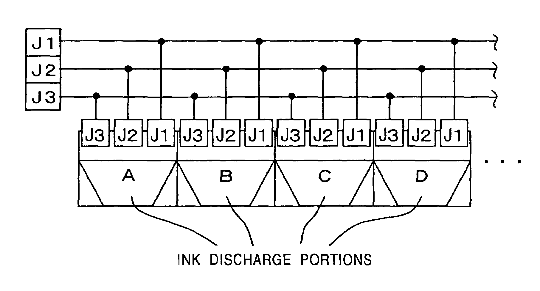
[0066]Description will be made regarding a first embodiment of the present invention with reference to the drawings and the like. The first embodiment has been made generally in order to achieve the first object of the present invention. Note that the term “ink droplet” used here means a small amount (e.g., several picoliters) of ink (liquid) discharged from a nozzle 18 of a liquid discharge portion described later. Also, the term “dot” used here means a dot formed of one ink droplet discharged on a recording medium such as a printing paper sheet or the like. Also, the term “pixel” used here is the smallest increment of an image, and the term “pixel region” used here means a region for forming the pixels.

[0067]In general, a predetermined number of liquid droplets (0, 1, or more) are discharged onto each pixel region, whereby a pixel with a predetermined tone level (tone level, 1, 2, 3, or more) is formed on each pixel region. That is to say, one pixel region has zero, one, or more d...

second embodiment

[0217]Next, a second embodiment according to the present invention will be described. Note that description of the same configuration as with the first embodiment will be omitted.

[0218]It is a principal object of the present second embodiment to provide an arrangement wherein occurrence of defects in the image due to malfunctioning of the head, such as occurrence of streaks between the pixel columns or the like is suppressed, even in the event that malfunctioning such as non-discharge occurs in a part of the liquid discharge portions.

[0219]Furthermore, it is another object (secondary object) thereof to provide an arrangement wherein the irregularities in an array of landing positions of the liquid droplets are less conspicuous.

[0220]Accordingly, the arrangement according to the present embodiment includes the head 11 employing the discharge direction varying means described in the first embodiment, first discharge control means, second discharge control means, and third discharge co...


PUM


Abstract

With a liquid discharge device, a maximum of N liquid droplets are discharged so as to land within each pixel region for forming a pixel corresponding to the pixel region, a target landing position is selected at random for each liquid droplet, from M liquid landing position candidates, forming an array in the direction of an array of nozzles, determined such that at least a part of the landing liquid droplet region corresponding to each landing position candidate is included within the pixel region, and the discharge direction of the liquid droplet is controlled such that the liquid droplet lands at the determined target landing position. The liquid discharge device having such a configuration has the advantage of preventing occurrence of streaks between dot columns in a printed image due to irregularities in an array of discharge portions.

Description

BACKGROUND OF THE INVENTION[0001]1. Field of the Invention[0002]The present invention relates to a liquid discharge device and liquid discharge method for discharging liquid droplets, and more particularly to a liquid discharge device and liquid discharge method for providing improved image quality.[0003]2. Description of the Related Art[0004]In general, conventional ink jet printers, which are a kind of liquid discharge device, include a head wherein ink discharge portions, each having a nozzle, are linearly disposed. With such ink jet printers, minute liquid droplets (ink droplets) are discharged onto a recording medium such as a printing paper sheet or the like, disposed so as to face the nozzle face, from each ink discharge portion of the head, so as to form generally-round-shaped dots on the recording medium, such that image pixels are formed of single or multiple dots. Furthermore, the image pixels are two-dimensionally arrayed, thereby forming images or characters.[0005]On th...

Claims


Application Information

Patent Timeline
IPC IPC(8): B41J29/38B41J2/07B41J2/05B41J2/14B41J2/15B41J2/155B41J2/21
CPCB41J2/04505B41J2/04533B41J2/04541B41J2/04573B41J2/04578B41J2/0458B41J2/04581B41J2/14056B41J2/15B41J2/155B41J2/2132B41J2202/20B41J2/07
Inventor EGUCHI, TAKEOTAKENAKA, KAZUYASUUSHINOHAMA, IWAOIKEMOTO, YUICHIROOHZEKI, YUKIHIRO
Owner SONY CORP
Why Eureka
Try Eureka