Driving mechanism for fragrance dispenser

a dispenser and driving mechanism technology, applied in the field of fragrance dispensers, can solve the problems of inability to change the fragrance amount, noise production, and poor movement of the conventional structure, and achieve the effects of smooth driving movement of the dispenser, low noise production, and easy control of fragrance dispensing time and amoun

Inactive Publication Date: 2007-05-29
TSAY CHYUAN FENG
View PDF4 Cites 36 Cited by
  • Summary
  • Abstract
  • Description
  • Claims
  • Application Information

AI Technical Summary

Benefits of technology

[0005]Accordingly, it is an object of the present invention to provide a driving mechanism for fragrance dispenser, wherein the driving movement of the dispenser is smoother and the noise production is low, and the fragrance dispensing time and amount can be easily controlled. Another object of the present invention is to provide an improved structure of a driving mechanism for a fragrance dispenser, wherein the driving mechanism includes a base seat, a motor positioned at the bottom section of the base seat and the axle of the motor is in engagement with the main driven gear which is geared to a press rod with row of teeth, thereby the transmission of the motor causes the press rod to press against the press button of the fragrance bottle, and the noise can be reduced and the transmission of the mechanism is smooth.
[0006]Yet another object of the present invention is to provide a driving mechanism for a fragrance dispenser, wherein the base seat is provided with a protruded fragrance bottle fixing slot, facilitating the fixing of the fragrance bottle.
[0007]A further object of the present invention is to provide a driving mechanism for a fragrance dispenser, wherein the mechanism includes a microprocessor, CPU and memories forming into a control circuit, thereby, the number of working day, the total number of dispensing can be set and controlled.

Problems solved by technology

This conventional structure may produce poor movement as a result of poor engagement of gears.
Besides, noise is produced and the electronic circuit for such conventional fragrance dispenser can only provide timing setting and the remaining amount of fragrance cannot be contrary.

Method used


Image

  • Driving mechanism for fragrance dispenser
  • Driving mechanism for fragrance dispenser
  • Driving mechanism for fragrance dispenser

Examples


Embodiment Construction

[0016]The following descriptions are of exemplary embodiments only, and are not intended to limit the scope, applicability or configuration of the invention in any way. Rather, the following description provides a convenient illustration for implementing exemplary embodiments of the invention. Various changes to the described embodiments may be made in the function and arrangement of the elements described without departing from the scope of the invention as set forth in the appended claims.

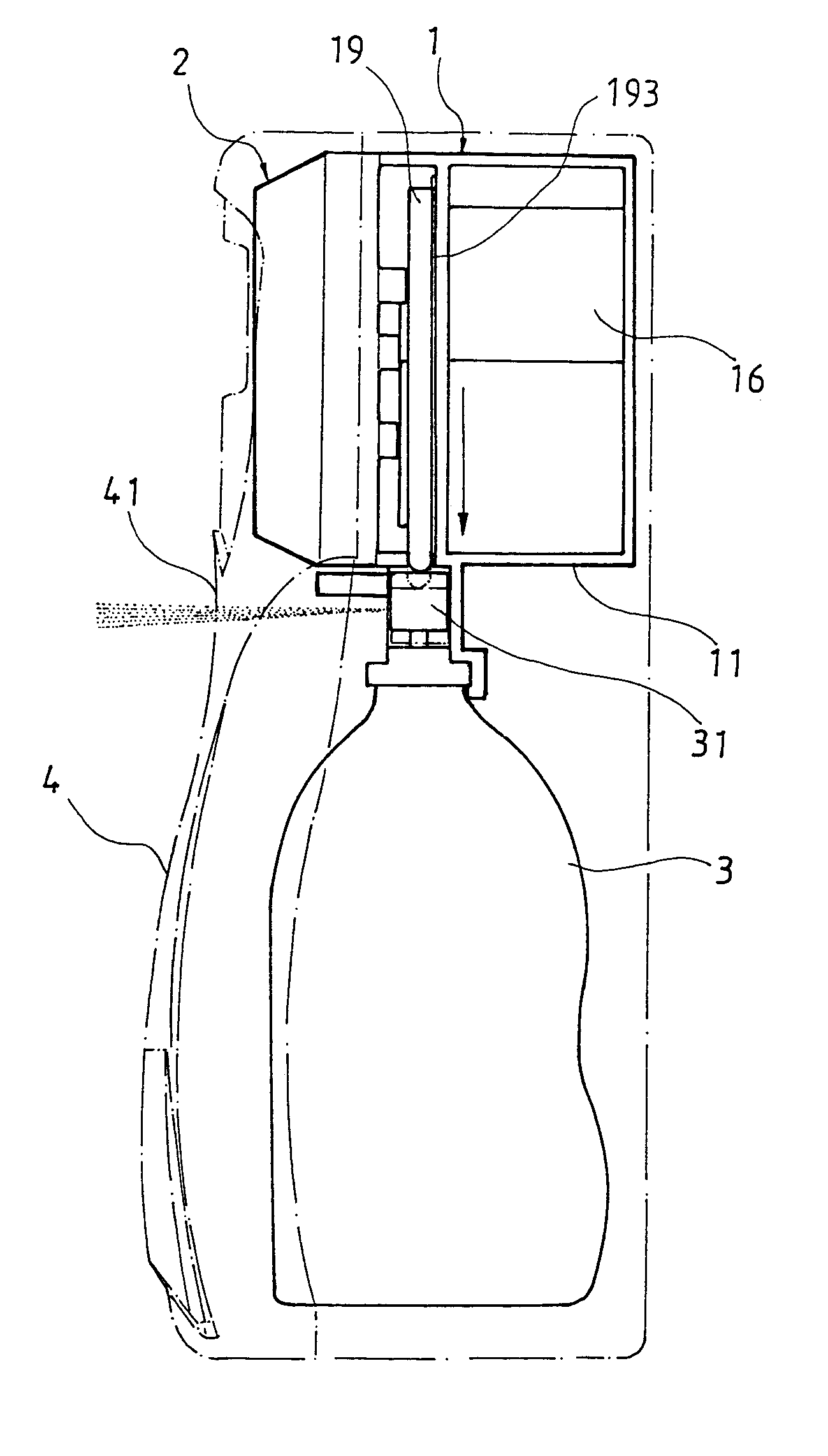
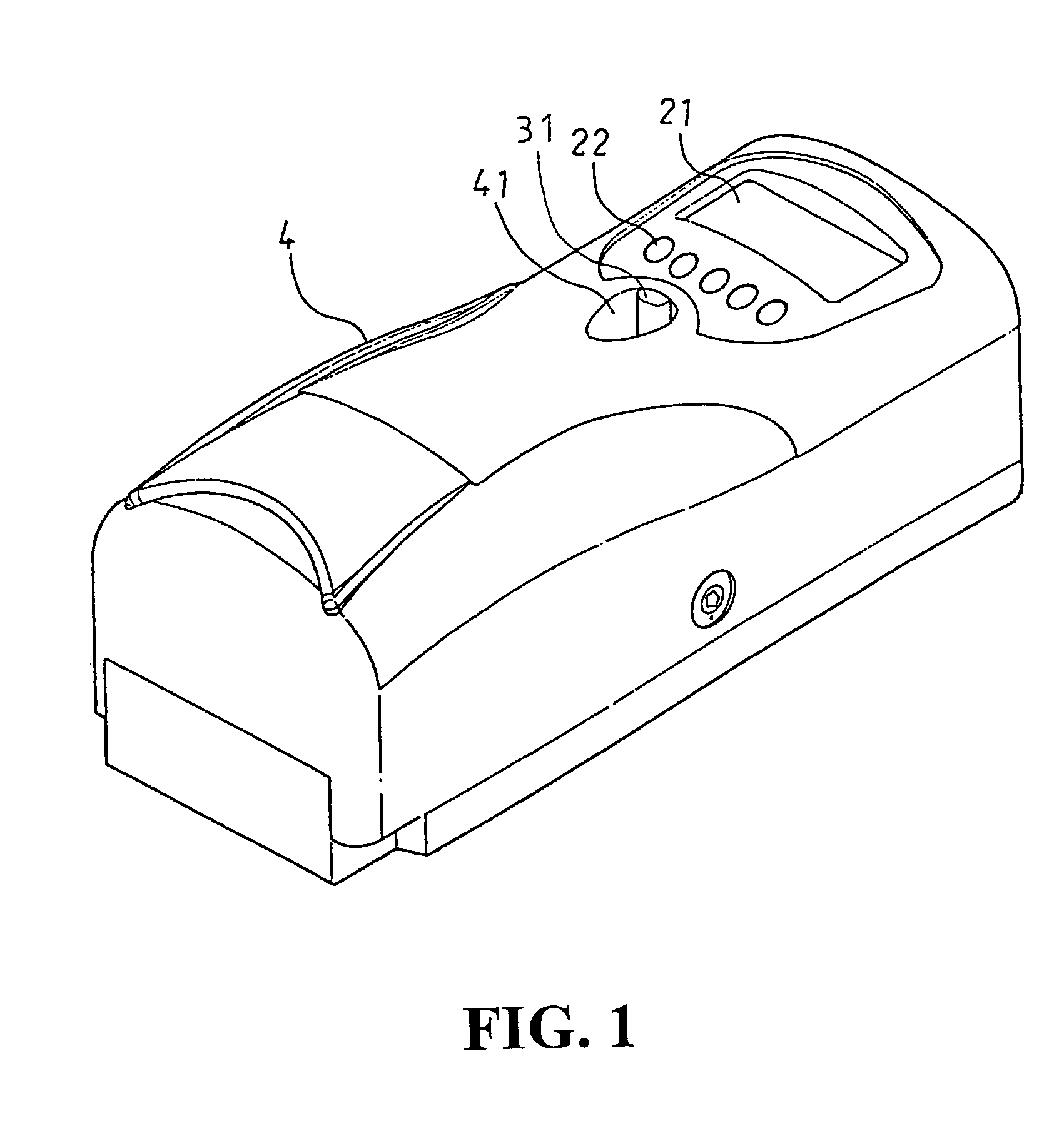
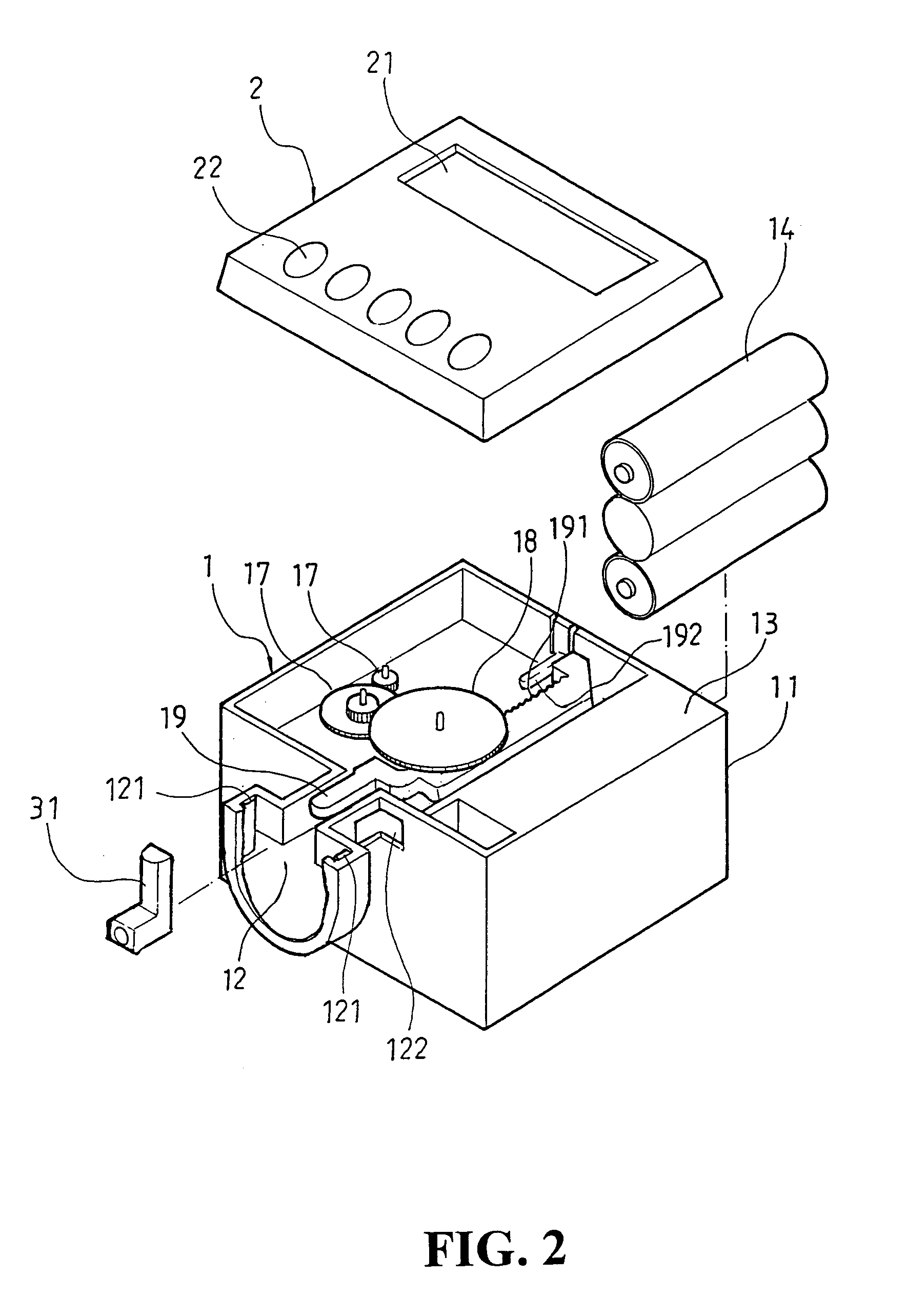
[0017]Referring to FIGS. 1, 2, 3 and 4, there is shown a driving mechanism for a fragrance dispenser which comprises a press mechanism 1, and a control circuit 2, wherein the press mechanism 1 includes a base seat 11 having a protruded circular recess 12 at the lower section of the base seat 11. The two lateral sides of the recess 12 are provided with fixing ribs 121, and at the connection between the recess 12 and the base seat 11 an opening 122 is formed. The opening 122 is used for the fixing ...


PUM


Abstract

A driving mechanism for fragrance dispenser is disclosed. The driving mechanism comprises a press mechanism and a control circuit characterized in that the press mechanism is provided with a base seat having a protruded circular recess at the lower section thereof for the mounting of a fragrance bottle, the surface of the base seat is mounted with engageable main and driven gears, and the bottom of the base seat is provided with a motor such that the axle of the motor and the main gear are engaged with each other, and the driven gear is engaged with a press rod having a plurality of teeth such that the driving by the control circuit will drive the gear to rotate and the press rod is driven to move up and down, thereby the dispensing head of the fragrance bottle is pressed and the fragrance is dispensed at a specific timing.

Description

BACKGROUND OF THE INVENTION[0001](a) Technical Field of the Invention[0002]The present invention relates to a fragrance dispenser, and in particular, to a fragrance dispenser which can be operated smoothly with low noise to dispense fragrance at a specific time.[0003](b) Description of the Prior Art[0004]Conventional fragrance dispenser is provided with a driving mechanism having gears to directly transmit the driving. After the motor of the dispenser is locked with a locking plate, the locking plate is then mounted onto a base seat. This conventional structure may produce poor movement as a result of poor engagement of gears. Besides, noise is produced and the electronic circuit for such conventional fragrance dispenser can only provide timing setting and the remaining amount of fragrance cannot be contrary. Accordingly, it is an object of the present invention to provide a driving mechanism for fragrance dispenser which mitigates the above drawbacks.SUMMARY OF THE INVENTION[0005]A...

Claims


Application Information

Patent Timeline
Patent Type & Authority Patents(United States)
IPC IPC(8): G04C23/00
CPCA61L9/14B05B11/3052B65D83/262G04C23/18B05B11/1052
Inventor TSAY, CHYUAN-FENG
Owner TSAY CHYUAN FENG
Why Eureka
Try Eureka