
Test output compaction using response shaper

a response shaper and output compactor technology, applied in the field of logic circuit design testing, can solve the problems of xbdist's output compactor only achieving a limited compression ratio, disadvantageous compression of compactors, and inability to avoid masking an even number of errors, so as to minimize the masking of faults, minimize the masking of errors, and minimize the effect of fault masking

Inactive Publication Date: 2007-05-22
NEC CORP
View PDF2 Cites 14 Cited by
  • Summary
  • Abstract
  • Description
  • Claims
  • Application Information

AI Technical Summary

Benefits of technology

The present invention is about a logic testing architecture and a method of output compaction that can minimize the masking of faults. It uses a response shaper that receives output responses from scan chains and reshapes them in a way that reduces masking of errors caused by unknown values or even numbers of errors. This helps to improve the accuracy of logic testing. The invention can be used with simplistic compaction structures such as XOR trees and does not require specialized test patterns or tools. Overall, the invention provides a more efficient and accurate way to test logic circuits.

Problems solved by technology

Testing of complicated digital logic circuits requires the analysis of a large amount of test response data.
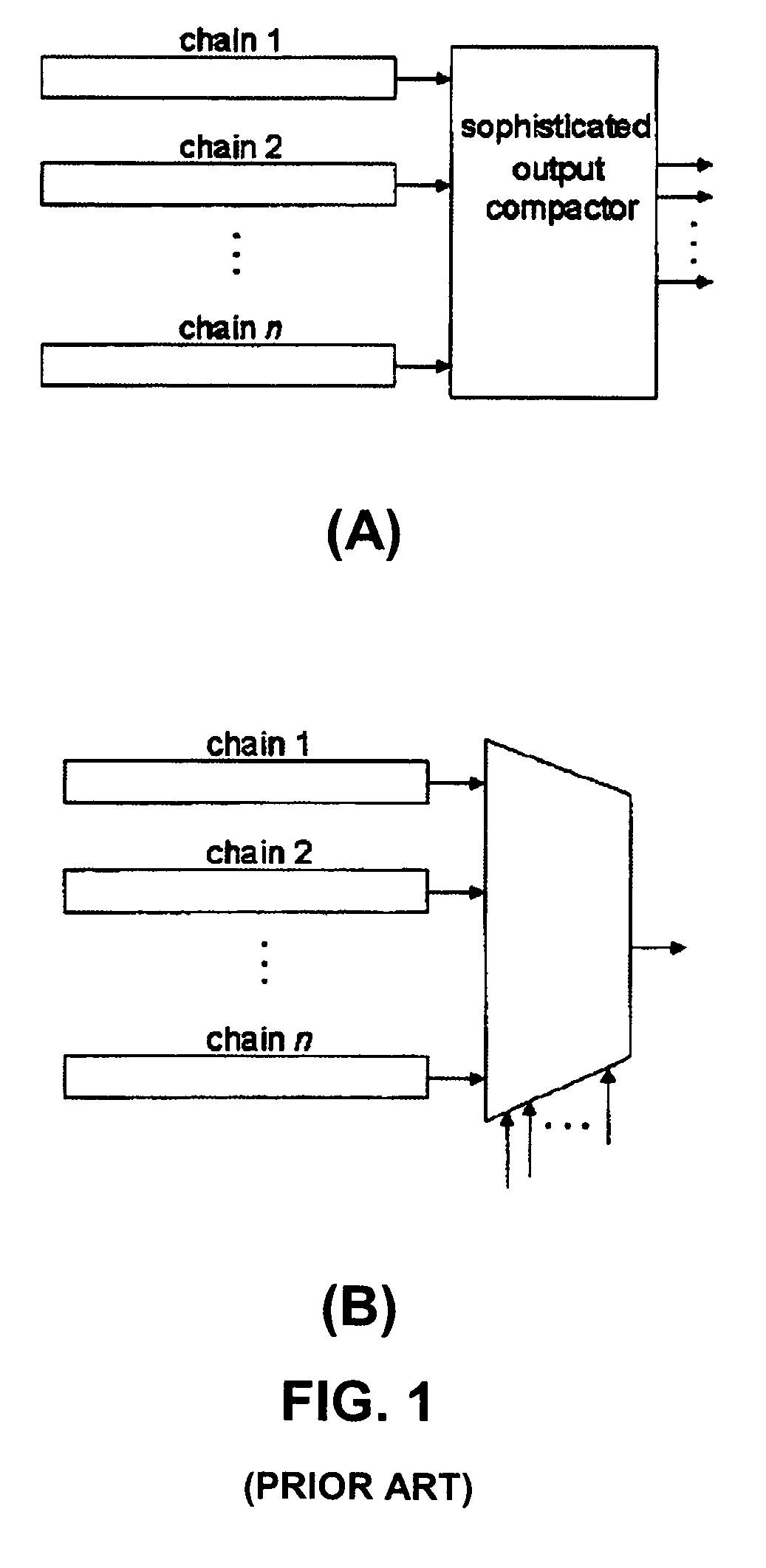
Unfortunately, such XOR-based output compactors disadvantageously can have decreased fault coverage caused by the masking of errors during a shift cycle.
Unfortunately, even such sophisticated output compactors, which use more XOR gates than a simple XOR tree, cannot avoid masking an even number of errors greater than two in a single shift cycle.
Although it can handle unknown values better than prior art XOR network-based output compactors, XBDIST's output compactor can only achieve a limited compression ratio and also requires additional test data to control the multiplexer and a special dedicated automatic test pattern generator (ATPG) that is compatible with the output compactor.

Method used


Image

  • Test output compaction using response shaper
  • Test output compaction using response shaper
  • Test output compaction using response shaper

Examples


Embodiment Construction

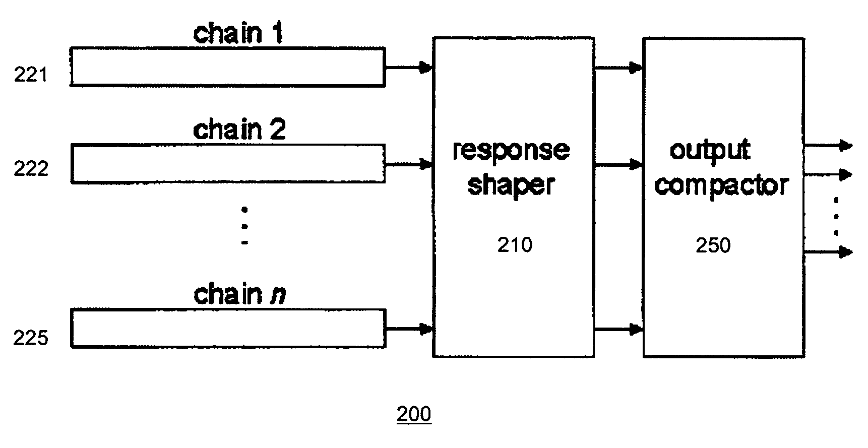
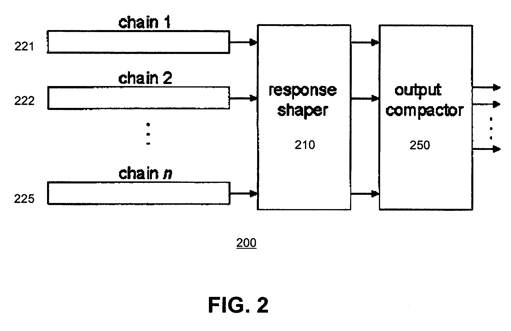
[0015]FIG. 2 is a block diagram illustrating an embodiment of the present invention. The output compaction architecture 200 comprises a response shaper 210 which is inserted between the outputs of the scan chains 221, 222, . . . , 225 and the inputs of the output compactor 250. The output compactor 250 advantageously need not be a sophisticated array of exclusive-OR (XOR) gates. In fact, the output compactor 250 can be implemented by any XOR network-based compactor and even the most primitive XOR tree. It is accepted that the output compactor 250 will allow some masking of faults to occur during compaction. The response shaper 210, the operation and design of which is further described in detail herein, serves to “reshape” responses from the scan chains 221, 222, . . . , 225 in a manner that preferably minimizes the masking of faults by the output compactor 250.

[0016]FIG. 3 through 5 illustrate the principles behind the reshaping of the scan chain responses. FIG. 3 depicts a simple ...


PUM


Abstract

A test output compaction architecture and method that takes advantage of a response shaper in order to minimize masking of faults during compaction. A response shaper is inserted between a plurality of scan chains and an output compactor. The response shaper receives output responses from scan chains and reshapes the output responses in a manner that minimizes masking of faults by the output compactor.

Description

BACKGROUND OF THE INVENTION[0001]The present invention is related to testing of logic circuit designs and, in particular, to compaction of test response data.[0002]Testing of complicated digital logic circuits requires the analysis of a large amount of test response data. A variety of output compaction techniques have been devised for reducing the size of test response data stored in test memory. Most output compaction techniques use combinational circuits, predominantly built of exclusive-OR (XOR) networks, to reduce the number of scan channels that will be observed by automatic test equipment (ATE) during test applications. Unfortunately, such XOR-based output compactors disadvantageously can have decreased fault coverage caused by the masking of errors during a shift cycle. If there are an even number of scan flip-flops that drive the same XOR tree and are scanned out at the same shift cycle, then the errors are masked out and cannot be observed by the ATE. Likewise, a circuit un...

Claims


Application Information

Patent Timeline
Patent Type & Authority Patents(United States)
IPC IPC(8): G01R31/28
CPCG01R31/318547
Inventor WANG, SEONGMOONCHAKRADHAR, SRIMAT T.CHAO, CHIA-TSO
Owner NEC CORP
Learn More