Water-injection rack base for mast
a technology of water injection rack and mast, which is applied in the direction of machine supports, furniture parts, other domestic objects, etc., can solve the problems of inconvenience in some extent, and achieve the effects of convenient packaging, transportation and storage, and convenient us
- Summary
- Abstract
- Description
- Claims
- Application Information
AI Technical Summary
Benefits of technology
Problems solved by technology
Method used
Image
Examples
examples
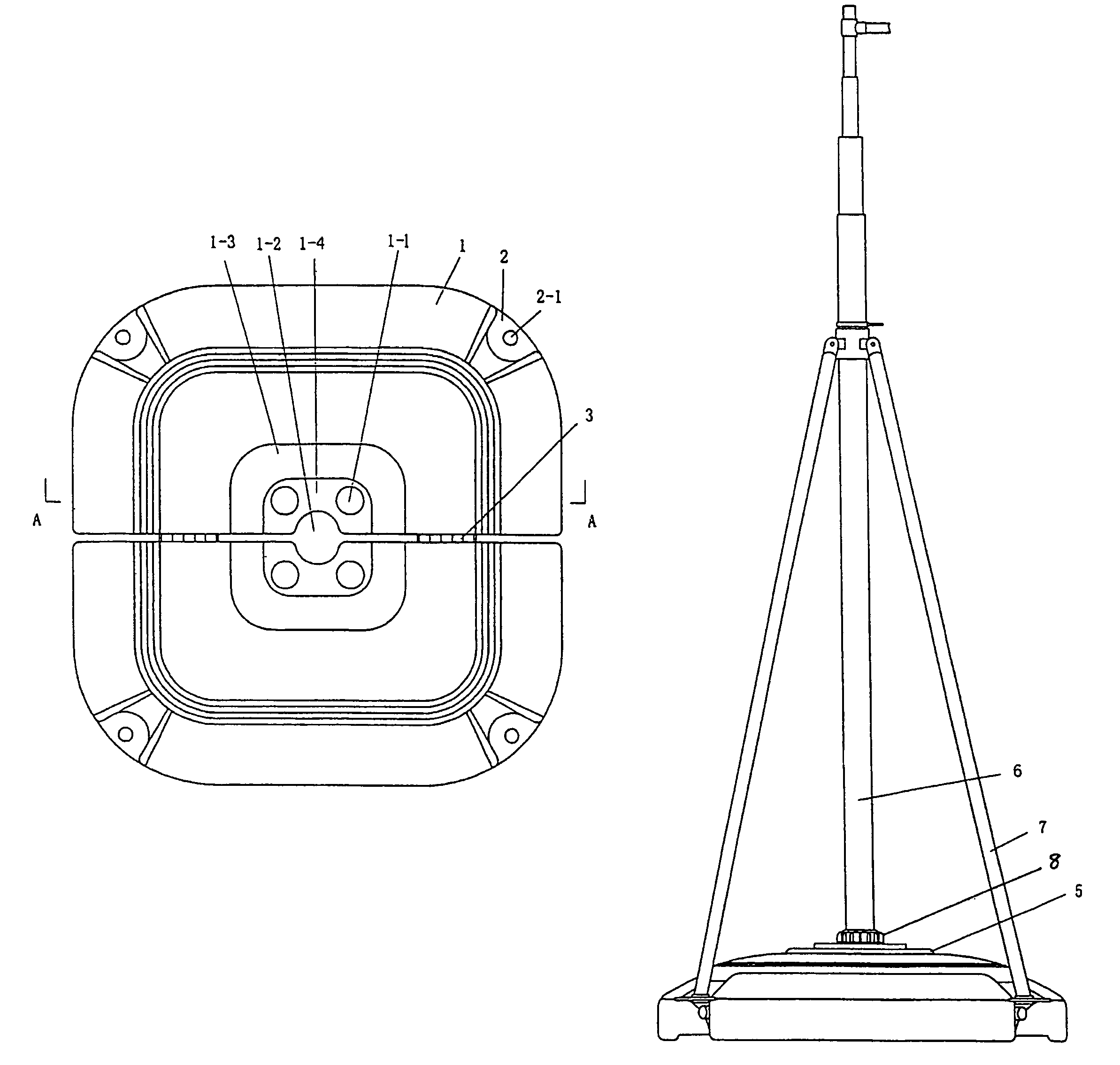
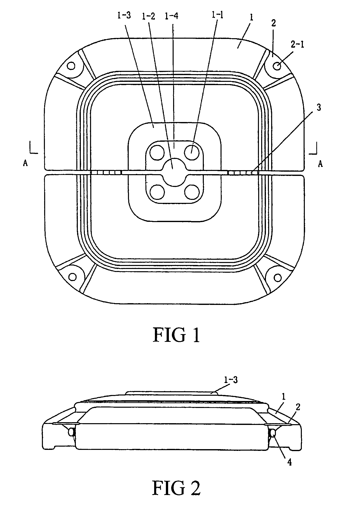
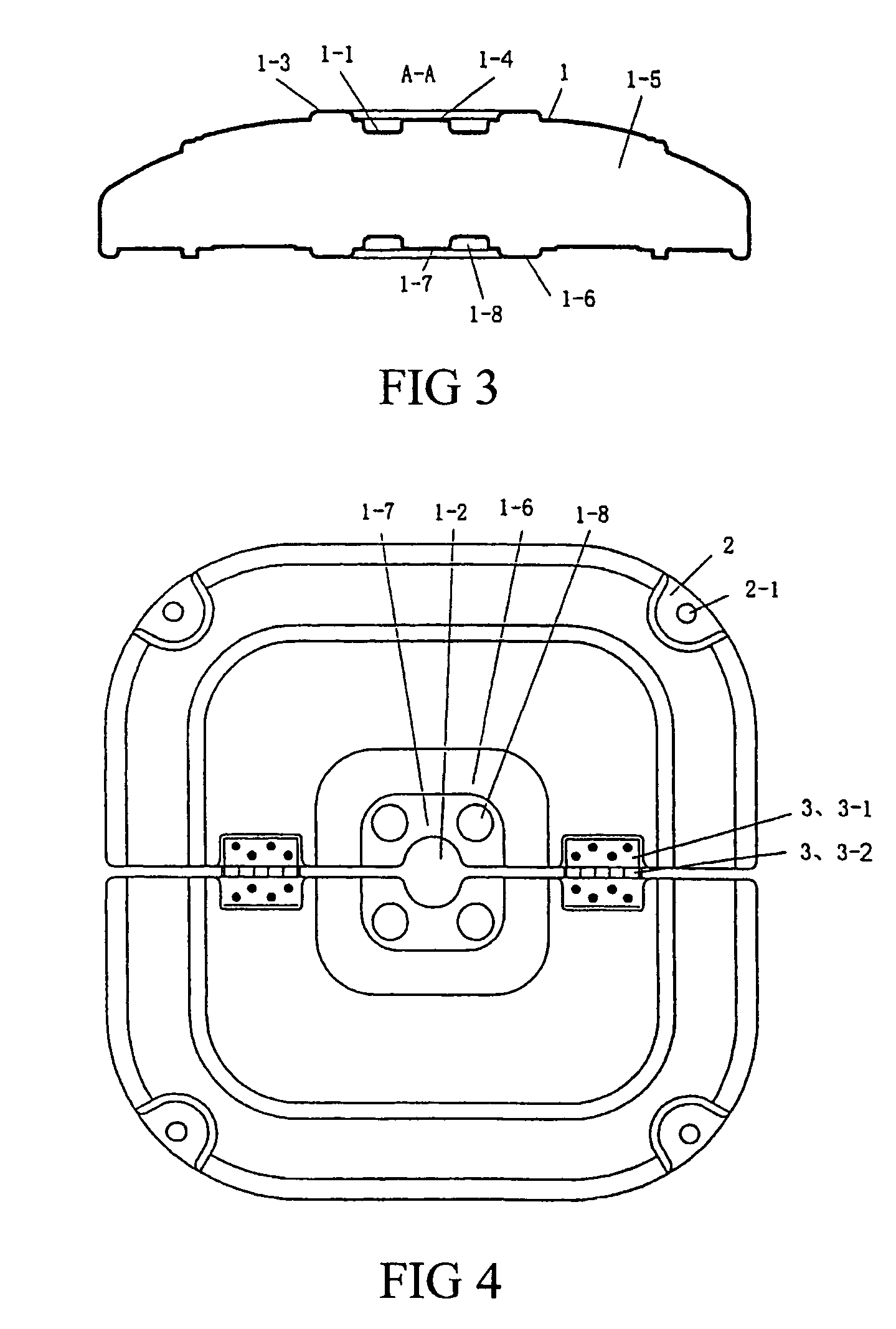
[0025]Examples shown in FIGS. 1–5 are composed of two semi-bases 1 each having a cavity 1-5 connected by hinge 3, and the hinge 3 comprises two leaves 3-1 and axle 3-2 connecting the two leaves, the two leaves 3-1 each being connected to the bottom surface of the two semi-bases 1, the two semi-bases 1 being able to rotate with respect to each other (see FIG. 5).
[0026]On the joint face of the two semi-bases and on the central position are provided semi-cylindrical concaves, thereby forming holes 1-2 on the top surface for inserting a mast when the two semi-bases are pulled open. All the outer corners of the two semi-bases 1 are recessed inward, and on the recesses are provided slabs 2, and on the slabs 2 are provided bracket holes 2-1. Water discharge holes are disposed on the two semi-bases and located under the slabs 2 at corners, and at the ports of the water discharge holes are provided covers 4.
[0027]On the top surfaces of the two semi-bases 1 each are provided a protrusion 1-3....
examples of application
[0029]FIG. 6 shows examples of application. When the two bases 1 are pulled open, the base 1 is injected with water through the water injection hole 1-1. Lock plates 5 are disposed on the low lying 1-4 of the top surface of the two semi-bases and on the low lying 1-7 of the bottom surface thereof, on the bottom surface of the upper lock plate 5 is provided a central protrusion 5-1 corresponding to the mast hole 1-2 and a peripheral protrusion 5-2 corresponding to the water injection hole 1-1. The structure of the lower lock plate is the same as the upper lock plate, and on its top surface is provided a peripheral protrusion corresponding to the blind hole 1-8 for positioning the lock plate. The upper and lower lock plates are covered on the low lying of the corresponding top surface and bottom surface, and the protrusions are inserted in corresponding holes. In the upper and lower lock plates and mast hole 1-2 is inserted a hollow bolt 8 in which the mast 6 is inserted. Four bracket...
PUM
 Abstract
Description
Claims
Application Information
 - R&D
- Intellectual Property
- Life Sciences
- Materials
- Tech Scout
- Unparalleled Data Quality
- Higher Quality Content
- 60% Fewer Hallucinations
Browse by: Latest US Patents, China's latest patents, Technical Efficacy Thesaurus, Application Domain, Technology Topic, Popular Technical Reports.
© 2025 PatSnap. All rights reserved.Legal|Privacy policy|Modern Slavery Act Transparency Statement|Sitemap|About US| Contact US: help@patsnap.com


