Material removing apparatus

a technology of material removal and removing utensils, which is applied in the direction of roofs, metal working equipment, construction, etc., can solve the problems of inconvenient use at elevated positions, damage to the underlying support surface of shingles, and low cost of gasoline used to power them

Inactive Publication Date: 2007-05-15
NELSON BRADLEY A
View PDF8 Cites 8 Cited by
  • Summary
  • Abstract
  • Description
  • Claims
  • Application Information

AI Technical Summary

Benefits of technology

[0013]A handle and an associated mounting bracket are included for securing the handle to the frame adjacent to the axle. Such a handle extends upwardly and rearwardly from the plate so that an operator can effectively control the direction of travel while standing rearwardly of the frame. The handle has a contoured rear portion for advantageously providing an area along which the operator can maintain an effective grip during operating conditions.
[0014]The apparatus further includes a lifting plate formed from hardened material extending forwardly from selected ones of the bracket end portions and spaced forwardly from the wheels. The lifting plate preferably includes a serrated edge provided with a plurality of teeth for advantageously engaging nails embedded through the shingles and the support surface. Such a plate is adjustably positionable medially of the shingles and the support surface for conveniently lifting the shingles upwardly and away from the support surface.
[0016]The plate further includes an outer shaft journaled about the inner shaft and rotatable about the fulcrum axis in clockwise and counter clockwise directions. The lifting plate has a substantially planar top surface for conveniently receiving and collecting the shingles thereon.
[0018]Preferably, an elongated support member having a threaded outer surface is adjustably securable to the rear frame portion. Such a support member has opposed end portions aligned along a substantially vertical axis and is engageable with a ground surface and the frame respectively so that a spatial relationship therebetween can be manually adjusted by the operator. The support member further includes an end cap attached to one of the end portions thereof for advantageously assisting the plate to pivot about the fulcrum axis during operating conditions.

Problems solved by technology

This method, however, can result in damage caused to the underlying support surface of the shingles and the gasoline used to power it is not cost-effective.
Another patent discloses a rather elaborate structure utilized for a continuous shingle removing process which is rather bulky and complex compared to other devices of similar design, thus making it inconvenient for use at elevated positions.
Such an apparatus possesses the same problem as the reciprocating apparatus mentioned above and poses a new problem by having to cope with an electrical wire while working.

Method used


Image

  • Material removing apparatus
  • Material removing apparatus
  • Material removing apparatus

Examples


Embodiment Construction

[0026]The present invention will now be described more fully hereinafter with reference to the accompanying drawings, in which a preferred embodiment of the invention is shown. This invention may, however, be embodied in many different forms and should not be construed as limited to the embodiment set forth herein. Rather, this embodiment is provided so that this application will be thorough and complete, and will fully convey the true scope of the invention to those skilled in the art. Like numbers refer to like elements throughout the figures.

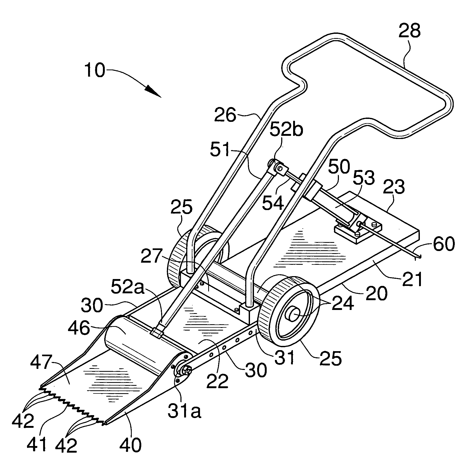
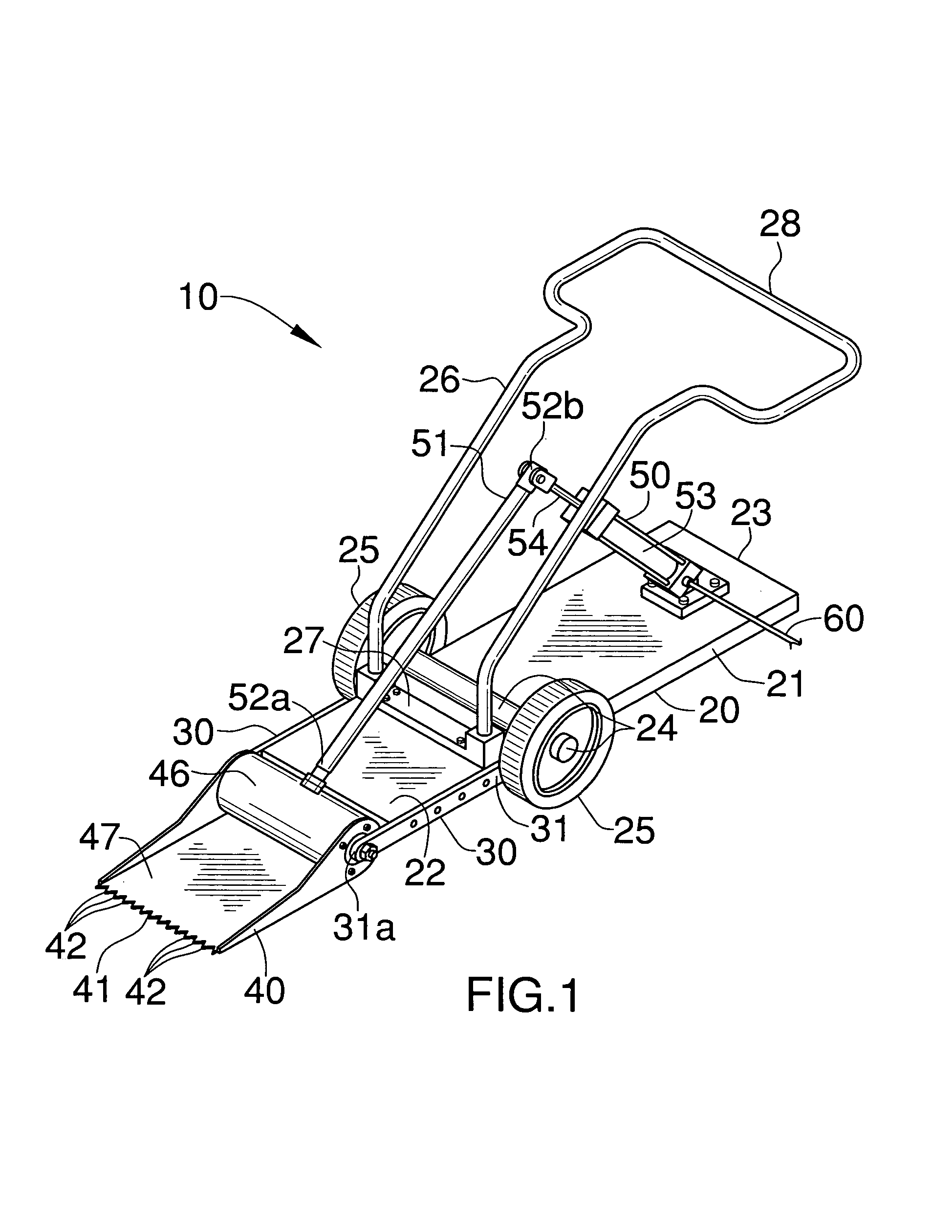
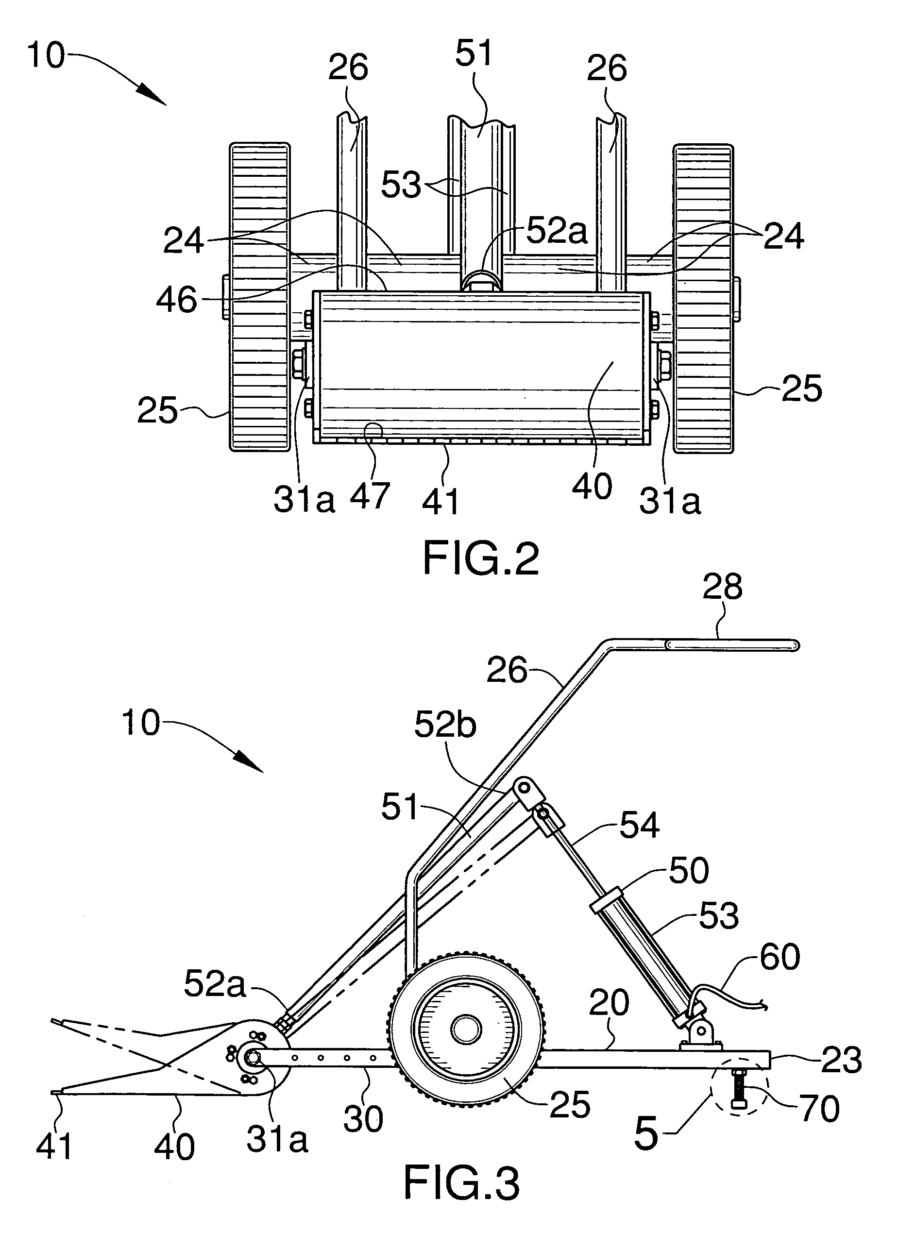
[0027]The apparatus of this invention is referred to generally in FIGS. 1–6 by the reference numeral 10 and is intended to provide a material removing apparatus. It should be understood that the apparatus 10 may be used to remove many different types of material and should not be limited to removing only roof shingles.

[0028]Referring initially to FIG. 1, the apparatus 10 includes a frame 20 sized and shaped for being pushed along a selected s...


PUM


Abstract

A material removing apparatus includes a frame including a planar base portion and axially spaced front and rear portions. An elongated axle and a plurality of wheels are attached thereto and a plurality of rigid brackets are secured to the axle adjacent to the wheels. A contoured handle is securely mounted to the frame. The apparatus also includes a lifting plate extending forwardly from the bracket end portions and spaced forwardly from the wheels for lifting shingles upwardly and away from a support surface. The plate includes an inner shaft having opposed end portions for defining a fulcrum axis and an outer shaft journaled about the inner shaft and rotatable about the fulcrum axis in clockwise and counterclockwise directions. A mechanism is included for pivoting the plate about a selected arcuate path so that an operator can position the plate between the support surface and the shingles.

Description

CROSS REFERENCE TO RELATED APPLICATIONS[0001]Not Applicable.STATEMENT REGARDING FEDERALLY SPONSORED RESEARCH OR DEVELOPMENT[0002]Not Applicable.REFERENCE TO A MICROFICHE APPENDIX[0003]Not Applicable.BACKGROUND OF THE INVENTION[0004]1. Technical Field[0005]This invention relates to a material removing apparatus and, more particularly, to a material removing apparatus for removing fastened shingles from a support surface.[0006]2. Prior Art[0007]It is a common practice to use hand tools on the order of pry bars and shovels for the removal of shingles. It is noted that numerous patents disclose portable, reciprocating roof shingle removing structures. One example is a gasoline operated structure utilizing reciprocating blade members to be placed underneath the roofing shingles to be removed by utilizing an agitating and generally reciprocating type movement. This method, however, can result in damage caused to the underlying support surface of the shingles and the gasoline used to power...

Claims


Application Information

Patent Timeline
IPC IPC(8): E04D15/00
CPCE04D15/003
Inventor NELSON, BRADLEY A.
Owner NELSON BRADLEY A
Why Eureka
Try Eureka