
Liquid dispensing system having a modular cord set

a liquid dispensing system and modular technology, applied in the direction of insulated conductors, cables, coupling device connections, etc., can solve the problems of slow service and repair procedures of hard wired electrical connections, hard wired connections, and discontinuation of attractive force, so as to promote quick and easy removal and replacement, easy to service, and easy to separate from the manifold

Inactive Publication Date: 2007-05-08
NORDSON CORP
View PDF14 Cites 4 Cited by
  • Summary
  • Abstract
  • Description
  • Claims
  • Application Information

AI Technical Summary

Benefits of technology

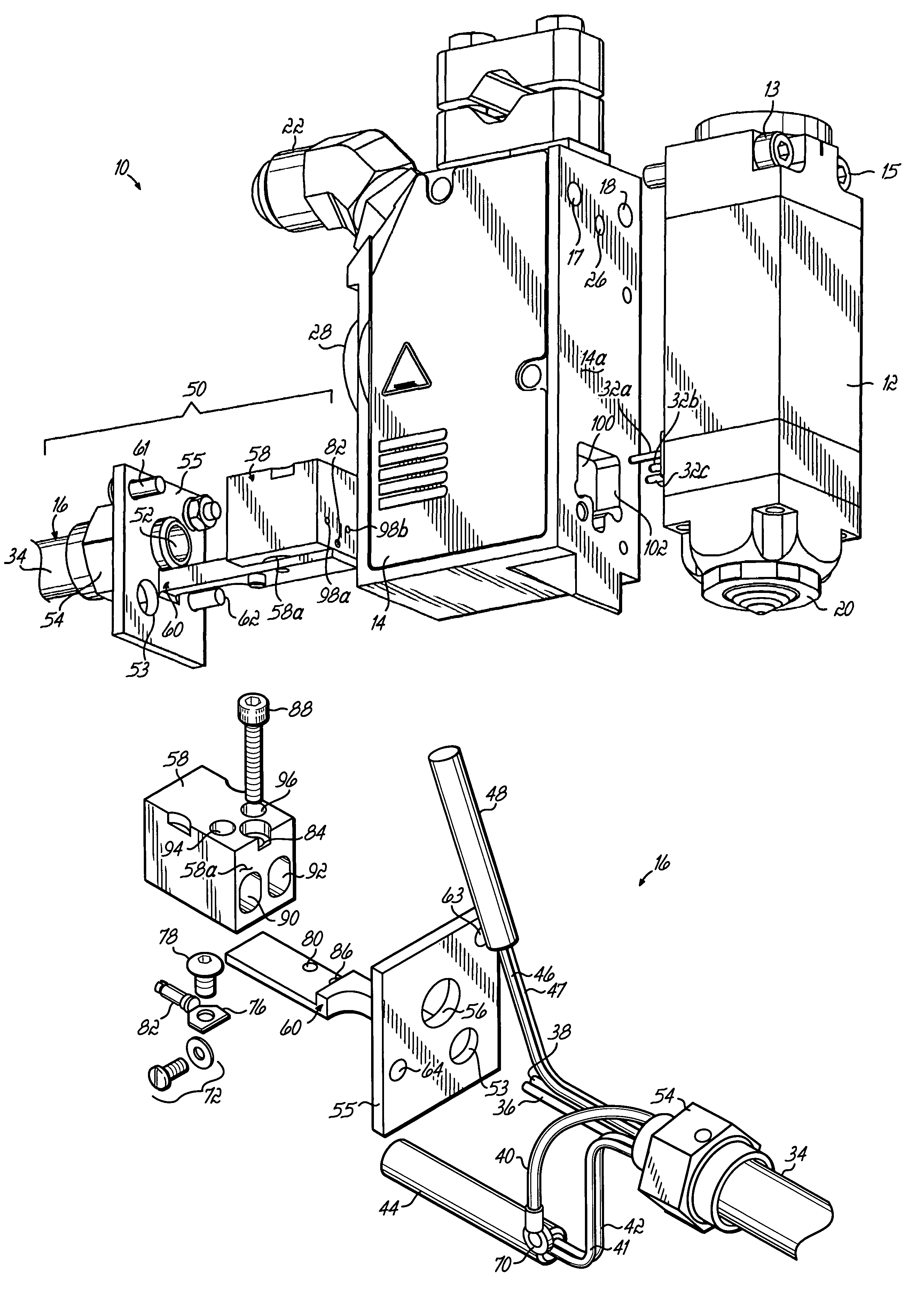
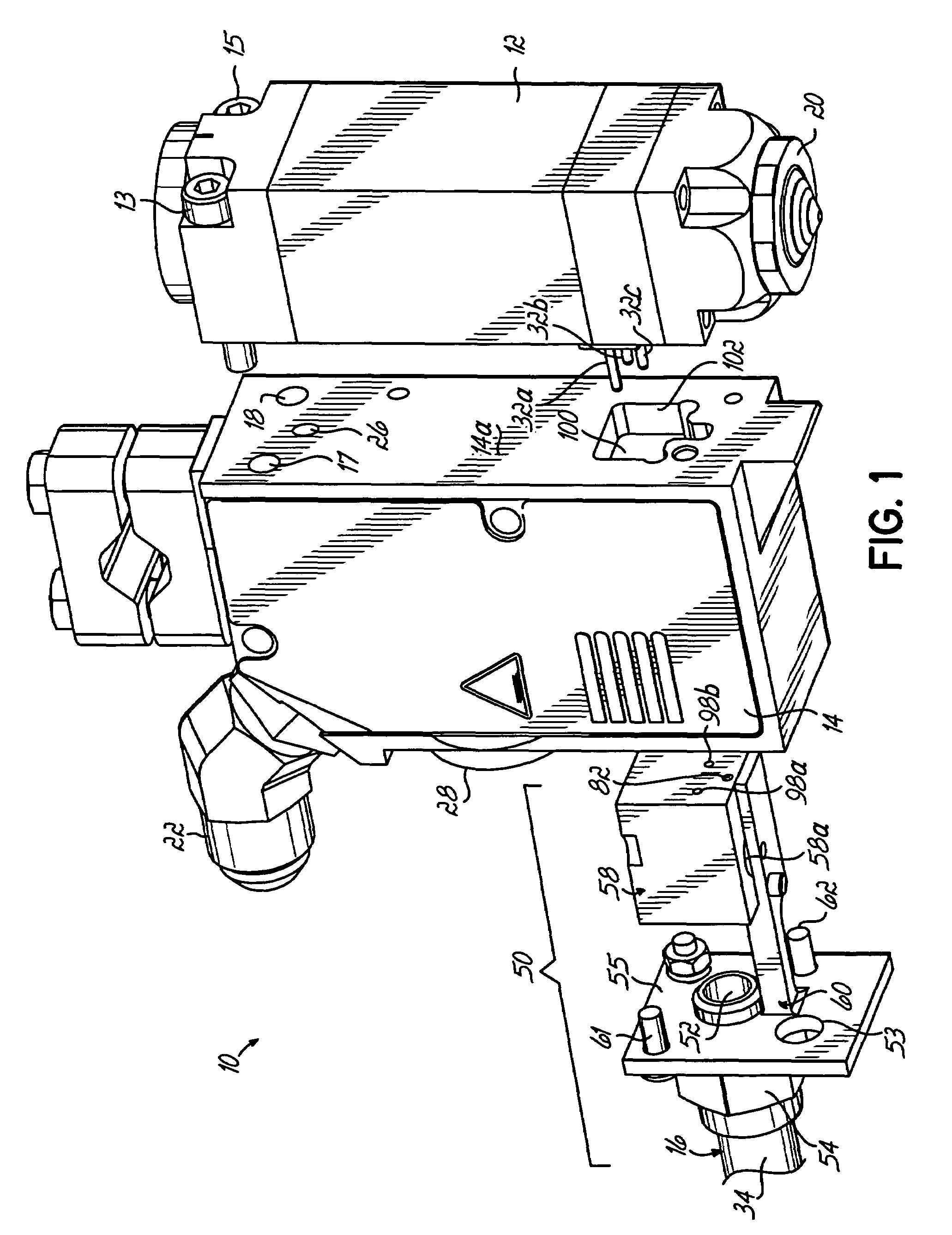
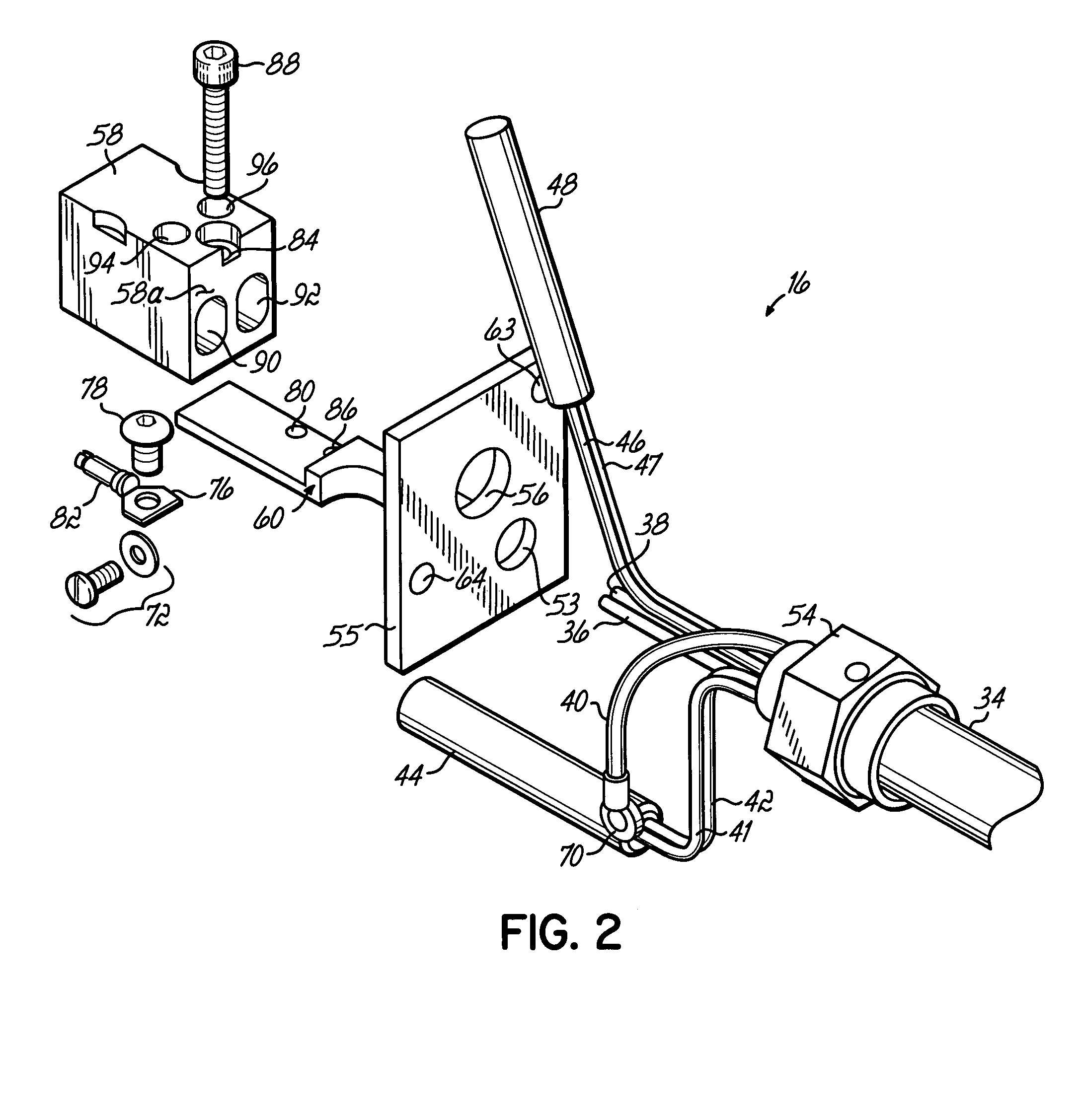
[0008]The present invention promotes quick and easy removal and replacement of a cord set from an assembled manifold and module. Because of the modularity in design, the module is easily separated from the manifold without disconnecting the cord set. As a result, the dispensing system may be readily serviced in the field. The manifold is provided with a receptacle that permits an electrical connector of the cord set to be easily engaged with, and disengaged from, the module and manifold. The modular design eliminates the hard wiring of these electrical connections found in conventional dispensing systems. Accordingly, the cord set and the manifold may be coupled and uncoupled by sliding a plug of the electrical connector relative to a receptacle defined in the manifold so that the contacts on the connector engage or disengage contacts on the module. The plug of the electrical connector itself is shaped to fit within the receptacle such that the electrical contacts on the plug are self-aligned with the electrical contacts on the module.

Problems solved by technology

When the electromagnetic coil is de-energized, the magnetization of the armature and pole piece rapidly dissipates, which discontinues the attractive force.
Conventional electrical connections are hard-wired connections, which are cumbersome when assembling and disassembling the dispensing module from the manifold and when engaging and disengaging the cord set from the manifold.
It follows that such conventional hard-wired electrical connections slow service and repair procedures.

Method used


Image

  • Liquid dispensing system having a modular cord set
  • Liquid dispensing system having a modular cord set
  • Liquid dispensing system having a modular cord set

Examples


Embodiment Construction

[0015]With reference to FIGS. 1 and 2, a liquid dispensing system 10 includes an electrically-operated gun or dispensing module 12, a manifold 14, and a cord set 16 extending to a controller (not shown). The cord set 16 includes an electrical connector (not shown) that physically and electrically couples with the cord set 16 with the controller. The module 12 may be physically connected with the manifold 14 in a variety of ways. For example, as shown in FIG. 1, two bolts 13, 15 are fastened into threaded openings 17, 18 of the manifold 14. Another bolt (not shown) extends through a countersunk clearance hole 19 extending through the module 12 and fastens into a threaded opening (not shown) having an entrance on the face of the module 12 confronting the manifold 14. As known to one of ordinary skill, the liquid dispensing system 10 of FIG. 1 may be used to dispense hot melt adhesive, paints, inks, other adhesives, as well as a variety of other liquids.

[0016]The module 12, manifold 14...


PUM


Abstract

A liquid dispensing system equipped with a modular cord set for powering an electrically-operated dispensing module of the system. The cord set includes a plug removably inserted into receptacle extending through a manifold of the system. The manifold heats and supplies liquid to the dispensing module. When the plug is positioned in the receptacle, electrical contacts on the plug are coupled with corresponding electrical contacts on the dispensing module. The cord set and dispensing module can be independently disconnected from the manifold without disturbing each other.

Description

FIELD OF THE INVENTION[0001]The invention generally relates to dispensing apparatus for dispensing flowable materials and, more particularly, to electrically-operated dispensing modules for dispensing viscous liquids like hot melt adhesives.BACKGROUND OF THE INVENTION[0002]Electrically-operated dispensing modules have been developed for product assembly lines requiring precise and intermittent placement of small amounts of a viscous liquid, such as heated hot melt adhesives, at a high speed onto a substrate. Generally, electrically-operated dispensing modules include an electromagnetic coil, a magnetic pole piece, a magnetic armature movable relative to the pole piece, and a valve stem operatively coupled for cyclic movement with the armature. Selectively energizing and de-energizing the electromagnetic coil moves the armature relative to the pole piece. When energized to initiate a dispensing cycle, the electromagnetic coil produces an electromagnetic field that magnetizes the arma...

Claims


Application Information

Patent Timeline
Patent Type & Authority Patents(United States)
IPC IPC(8): B67D5/62B67D7/80
CPCB05C5/02H01R33/92
Inventor BYERLY, DAVID J.
Owner NORDSON CORP
Learn More