Image display apparatus

a technology of image display and apparatus, which is applied in the direction of television systems, instruments, printing machines, etc., can solve the problems of consuming a lot of power, unable to utilize light with a high efficiency, and the aforementioned illuminating system can only be produced through a complicated process, so as to achieve the effect of improving efficiency

Inactive Publication Date: 2007-05-08
SONY CORP
View PDF6 Cites 28 Cited by
  • Summary
  • Abstract
  • Description
  • Claims
  • Application Information

AI Technical Summary

Benefits of technology

[0037]The present invention has also another object to provide an image display device which includes a non-luminous reflection type spatial light modulating element, a light source to illuminate the reflection type spatial light modulating element, and a projection optical system, is not complicatedly constructed and can thus be produced, not by any complicated process of production, and can utilize illumination light with an improved efficiency.
[0050]In the image display device, a part, made unnecessary for image display, of the light having arrived at the reflection type spatial light modulating element is returned to the light source and then guided again to the reflection type spatial light modulating element. Thus, the illumination light can be utilized with an improved efficiency.

Problems solved by technology

However, it cannot utilize light with a high efficiency and consumes much power.
The aforementioned illuminating system can only be produced through a complicated process of production.
Thus, it is thus complicated to produce and expensive.
The circular polarization plate disclosed in the aforementioned Japanese Patent Application Laid Open No. 281814 / 1994 has no wavelength dependence but has no sufficient polarization splitting characteristic.
Therefore, it is difficult for the conventional image display device to have an improved efficiency of light utilization.
In the illuminating systems disclosed in the aforementioned Japanese Patent No. 2509372 and Japanese Patent Application Laid Open No. 281814 / 1994, the shape of a reflector used for the discharge lamp actually used as a light source or illumination of the reflection type spatial light modulating element by reflected light from the reflector is not so effective for an improved efficiency of light utilization as expected.
Also, in case the reflector is a parabolic mirror, a light beam emanated from a focal point will return to the focal point when it is reflected by the reflection type polarization plate, but a light beam emanated from any other point than the focal point will not always return to the point from which it has being emanated when it is reflected by the reflection type polarization plate.
As above, being disadvantageous in the efficiency of light utilization and manufacturing cost, the polarization changing element in the conventional illuminating system cannot return light to its source with a sufficient efficiency.
Also, in case the reflection type polarization plate has to be increased in area, the optical parts included in this illuminating system will be very expensive.
Further, the light returned to the light source will possibly cause the illuminance to be nonuniform at the reflection type spatial light modulating element.
At this time, in case the optical axis of the optical system downstream of the fly-eye integrators is displaced only in one of longitudinal and lateral directions perpendicular to the optical axis, it is difficult to sufficiently reflect the light having returned to the light source.
Also, in case all the optical parts such as the projection optical system etc. located downstream of the fly-eye integrators are displaced in relation to the optical system including the light source and extending to the fly-eye integrators, all the optical systems will not possible be in line with each other.
In this case, a support mechanism to support the optical systems will be extremely complicated and include many parts.
The support mechanism will be difficult to produce.

Method used


Image

  • Image display apparatus
  • Image display apparatus
  • Image display apparatus

Examples


Embodiment Construction

[0090]The image display device according to the present invention will be described in detail below with reference to the accompanying drawings.

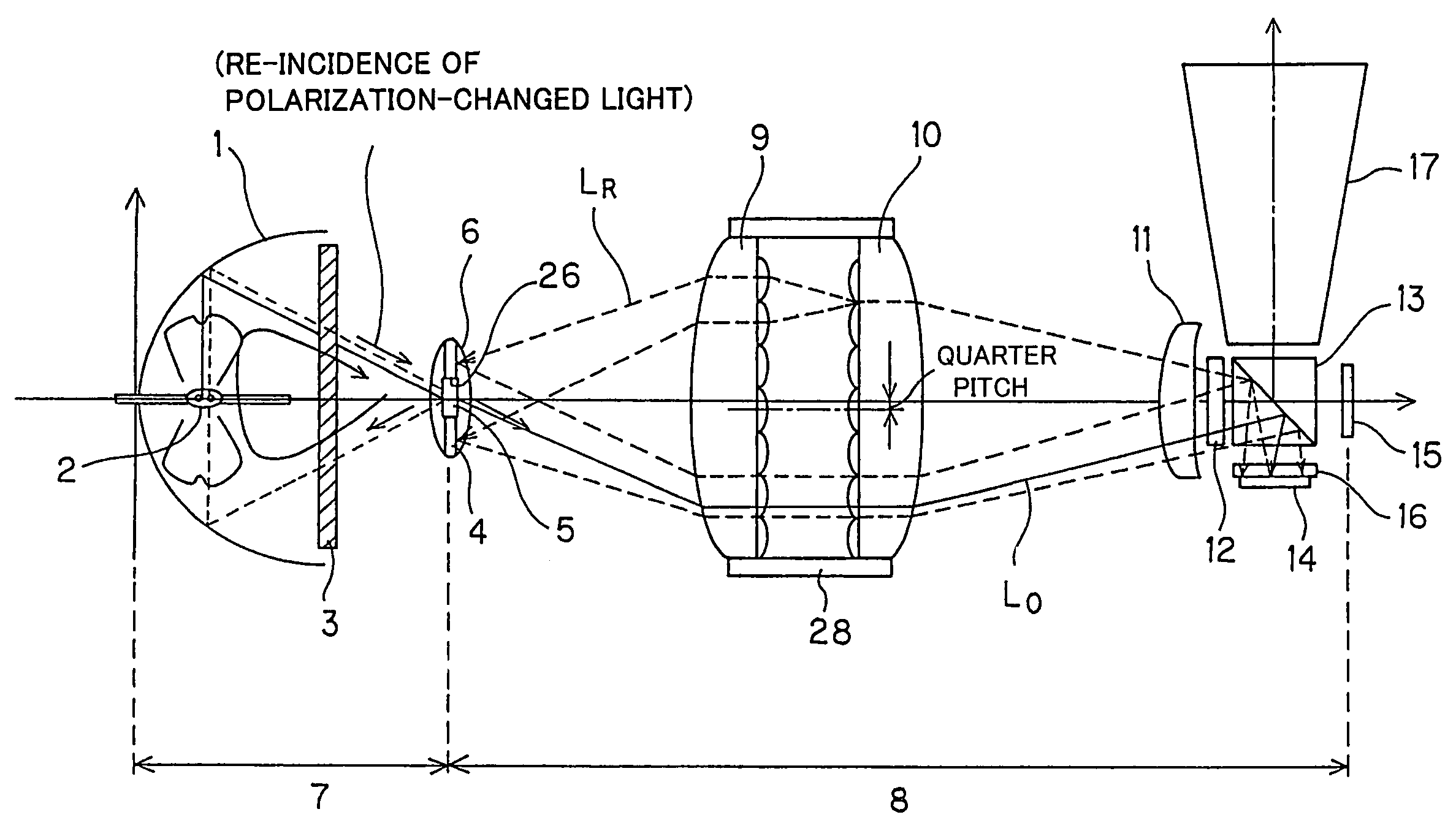
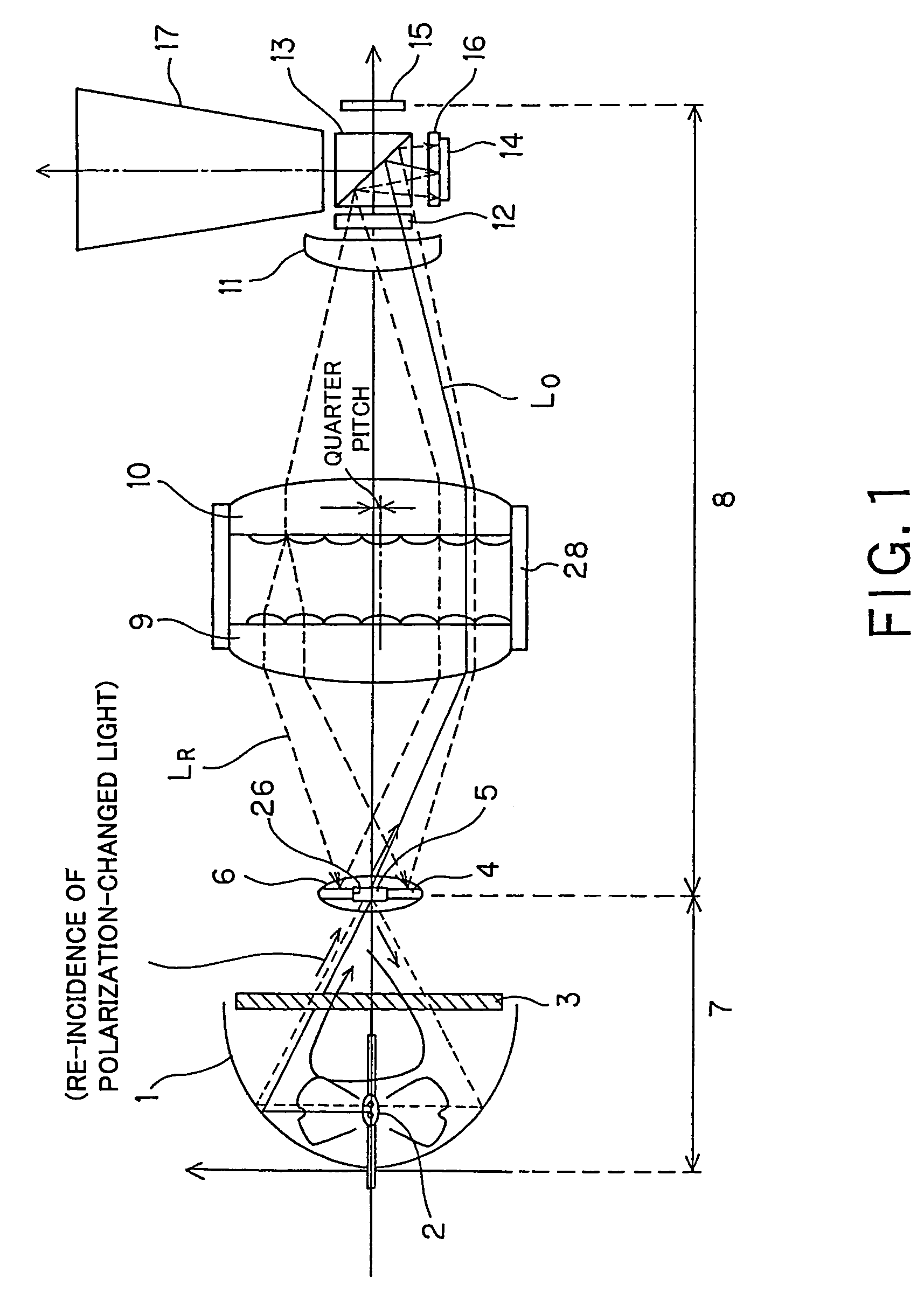
[0091]As shown in FIG. 1, the image display device according to the present invention includes a spheroidal reflecting mirror 1 having a spheroidal shape and open at the end thereof, and a light source 2 disposed on a first focal point of the spheroidal reflecting mirror 1. The light source 2 is a discharge lamp such as a UHP (ultra-high pressure mercury) lamp.

[0092]At the open end of the spheroidal reflecting mirror 1, there is provided a polarization changing element 3. As shown in FIG. 2, the polarization changing element 3 includes a quarter or half wave plate having an even number of areas extending radially and symmetrically with respect to the optical axis.

[0093]Near a second focal point of the spheroidal reflecting mirror 1, there is provided a relay lens block 6 having an opening 26 formed in the center thereof and having disposed t...


PUM

PropertyMeasurementUnit
angleaaaaaaaaaa
diameteraaaaaaaaaa
diameteraaaaaaaaaa

Abstract

According to the present invention, there is provided an image display device including a non-luminous reflection type spatial light modulating element, illuminating system to illuminate the reflection type spatial light modulating element and a projection lens and in which light from a light source (2) illuminates the reflection type spatial light modulating elements (14, 15) via first and second fly-eye integrators (9, 10). An unnecessary part, not modulated, of the light reflected by the reflection spatial light modulating elements (14, 15) and further by a reflector (4) for recycling. Since the fly-eye integrators (9, 10) are displaced in relation to their optical axes, it is possible to utilize the light with an improved efficiency and prevent any nonuniform illumination from taking place.

Description

TECHNICAL FIELD[0001]The present invention relates to a projection type image display device including a reflection type spatial light modulating element illuminated by an illuminating system and a projection optical system that forms an image of the reflection type spatial light modulating element.[0002]This application claims the priority of the Japanese Patent Application No. 2002-363070 filed on Dec. 13, 2002, the entirety of which is incorporated by reference herein.BACKGROUND ART[0003]There has been proposed a projection type image display device including an illuminating system, a reflection type spatial light modulating element illuminated by the illuminating system and a projection optical system (projection lens) that forms an image of the reflection type spatial light modulating element. Using a discharge lamp as the light source of the illuminating system and a liquid crystal element as the reflection type spatial light modulating element, such an image display device is...

Claims


Application Information

Patent Timeline
Patent Type & Authority Patents(United States)
IPC IPC(8): G03B21/26F21V7/00G02F1/00G02F1/1335G03B21/20G03B21/28G03B27/10G03B27/28G02B5/30H04N5/74G02B19/00G02B27/18G02B27/28G03B21/00
CPCH04N5/7416G02B27/18G03B21/00
Inventor MATSUI, HIROAKIYANO, TOMOYAOHMURA, YUKIO
Owner SONY CORP
Why Eureka
Try Eureka