
Blast protection structures

a technology for protecting structures and blasts, applied in the direction of flexible container closures, transportation and packaging, sacks, etc., can solve the problem of insufficient quantity of water, and achieve the effect of reducing the effect of blast escape, and reducing the construction difficulty

Active Publication Date: 2007-05-08
CINTEC INT
View PDF13 Cites 40 Cited by
  • Summary
  • Abstract
  • Description
  • Claims
  • Application Information

AI Technical Summary

Benefits of technology

[0005]According to the present invention, there is provided a blast protection structure comprising one or more rupturable containers, each of said rupturable containers being formed of a flexible bag having a aperture and filler cap so that fluid can be introduced into the bag and sealed therein, to give substantial rigidity to said rupturable container and to provide blast protection.
[0020]Apart from filler caps and drain plugs, there need be no rigid parts so that, in the event of a blast, there is initially no hazard from flying shards of metal or substantially rigid plastics material.

Problems solved by technology

However there may be occasions when water is insufficient in quantity or is even not available, but there is a compressor available.

Method used


Image

  • Blast protection structures
  • Blast protection structures

Examples


Embodiment Construction

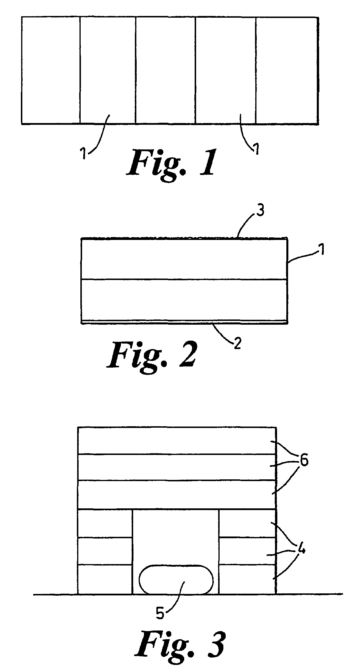
[0026]The path of FIG. 1 is made up from a plurality of elongate watertight bags 1, transverse to the direction of the path. When empty they can be rolled up, and when rolled out flat they can be filled with water sequentially so that each bag becomes hard, but not absolutely rigid. They are preferably made of drop-stitch material, as mentioned above, so that the path is generally flat.

[0027]Each bag is double chambered, one above the other as shown in FIG. 2. The underside 2 is sheathed in the material known as Kevlar, as protection against rough surfaces and for blast mitigation. The upper surface 3 has a non-slip coating or layer applied to it. Typically the total depth might be of the order of 200 mm (each chamber 100 mm) and the dimension in the longitudinal direction of the path 1.45 m. The width can be selected as desired.

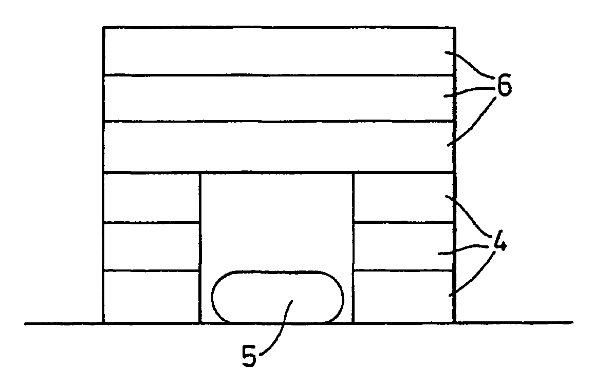
[0028]In FIG. 3, a set of annular bags 4 can be built up into a drum-like wall to surround a device 5 that might explode. This wall is capped by several dis...


PUM


Abstract

A blast protection structure is formed of one or more bags, generally shown as (1) in FIG. 2. Such bags comprise an upper and lower compartment, with the lower compartment having a reinforcing layer (2), preferably formed of an impact reactant structure such as Kevlar®. The upper surface (3) of the upper compartment, has a non-slip coating to provide improved stacking of bags. Such bags can be used to provide blast protection structures to minimize the risk of damage from an explosion.

Description

BACKGROUND OF THE INVENTION[0001]This invention relates to blast protection structures and in particular to bags used to make blast protection walls and roadways.[0002]A classic temporary blast protection wall is made of sandbags. Although sandbags are of proven value, they do have drawbacks. They are time consuming and not that easy to fill. They generally have to be filled at least a short distance away from where the wall is to be built, and hence have to be carried there after filling. Further, a suitable filling material is not always readily available, and once the need for the wall is over, emptying the bags and disposing of the filling material can be as problematic as filling them and building the wall in the first place.[0003]An alternative that has been in more recent use, comprises tanks of water, built up like bricks. The tanks are generally of black or at least dark plastics material and are substantially rigid. They are fairly light when empty, and so courses of tanks...

Claims


Application Information

Patent Timeline
IPC IPC(8): F42B33/00E04H9/04F42D5/045
CPCE04H9/04F42D5/045F41H5/24
Inventor JAMES, PETER
Owner CINTEC INT
Learn More