
Lock guard system

a technology of lock guards and guards, applied in the field of door lock devices, can solve the problem of not being able to efficiently secure the dead bolt lock mechanism from outside access,

Inactive Publication Date: 2007-05-01
NOKLEBERG ALBERT J
View PDF32 Cites 6 Cited by
  • Summary
  • Abstract
  • Description
  • Claims
  • Application Information

AI Technical Summary

Benefits of technology

[0010]In view of the foregoing disadvantages inherent in the known types of door lock devices now present in the prior art, the present invention provides a new lock guard system construction wherein the same can be utilized for efficiently securing a dead bolt lock mechanism from outside access.
[0016]A second object is to provide a lock guard system for efficiently securing a dead bolt lock mechanism from outside access.
[0018]An additional object is to provide a lock guard system that doesn't require additional drilling of the door.
[0019]A further object is to provide a lock guard system that is easily deactivated to allow normal usage.

Problems solved by technology

Unfortunately, dead bolt locks currently used today are able to be unlocked by those with a master key or those who can “pick” a lock to illegally gain access.
While these devices may be suitable for the particular purpose to which they address, they are not as suitable for efficiently securing a dead bolt lock mechanism from outside access.
Current dead bolt locks on doors do not always stop those with master keys or those who are able to “pick” a lock from gaining access.

Method used


Image

  • Lock guard system
  • Lock guard system
  • Lock guard system

Examples


Embodiment Construction

A. Overview

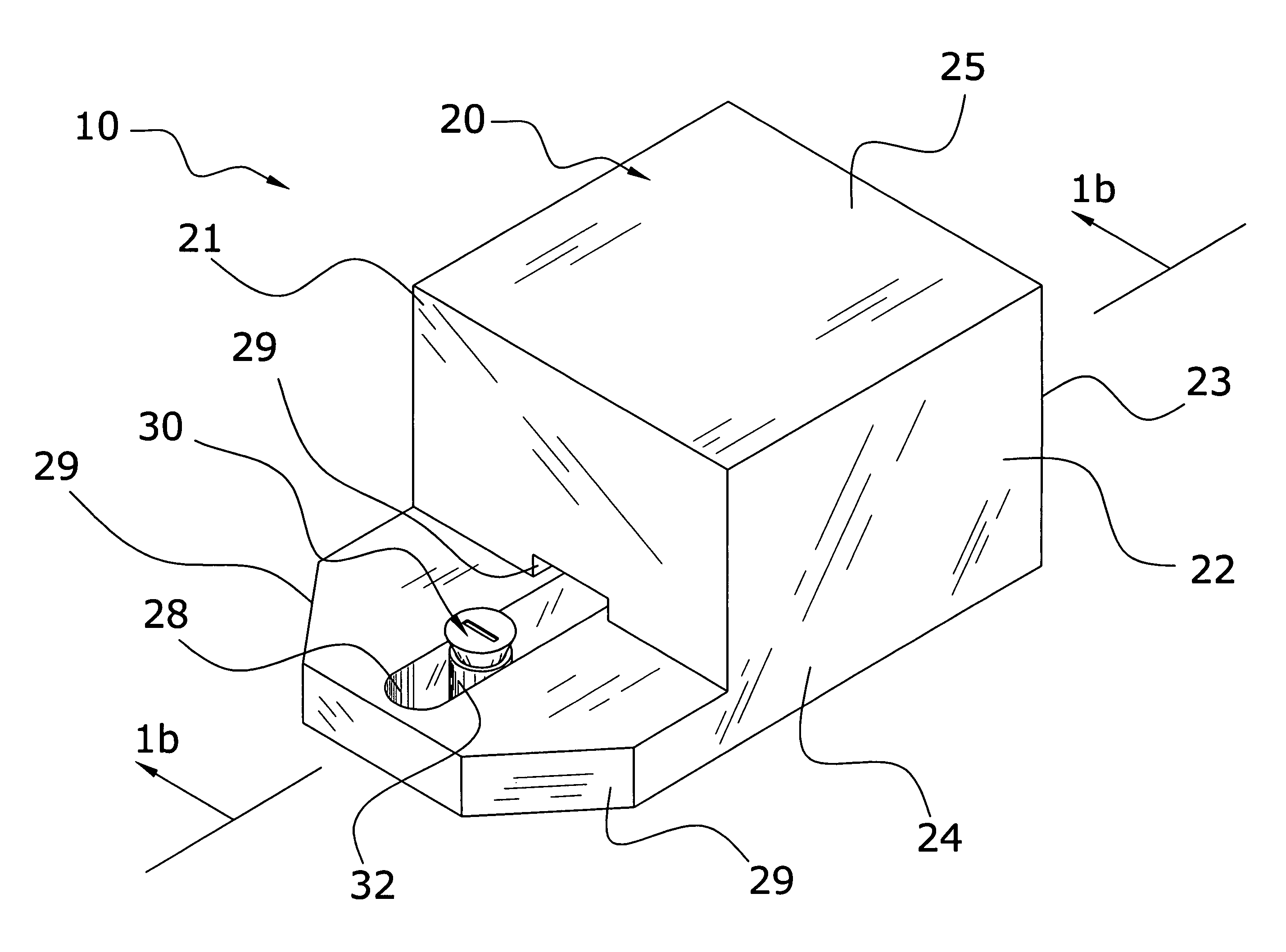
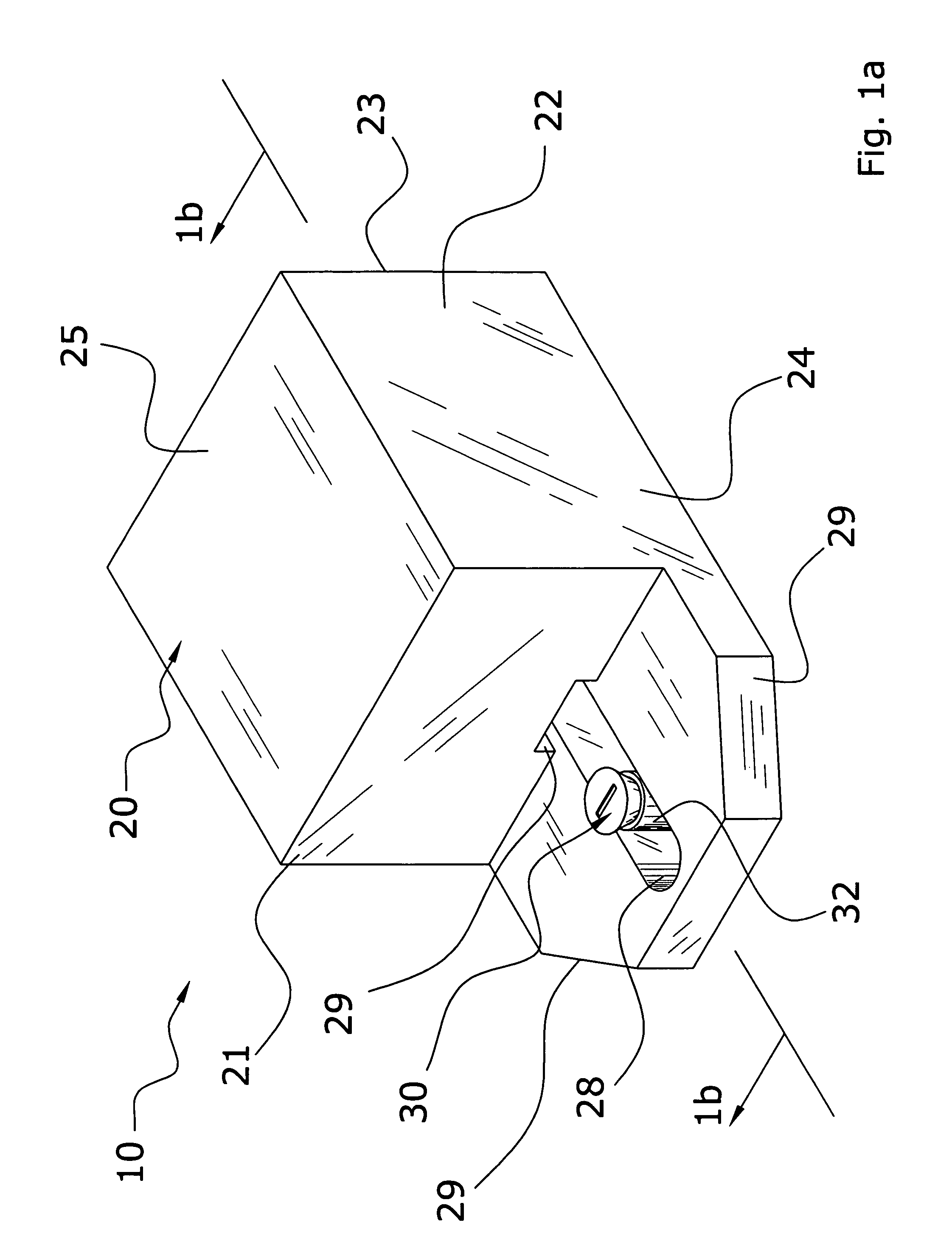
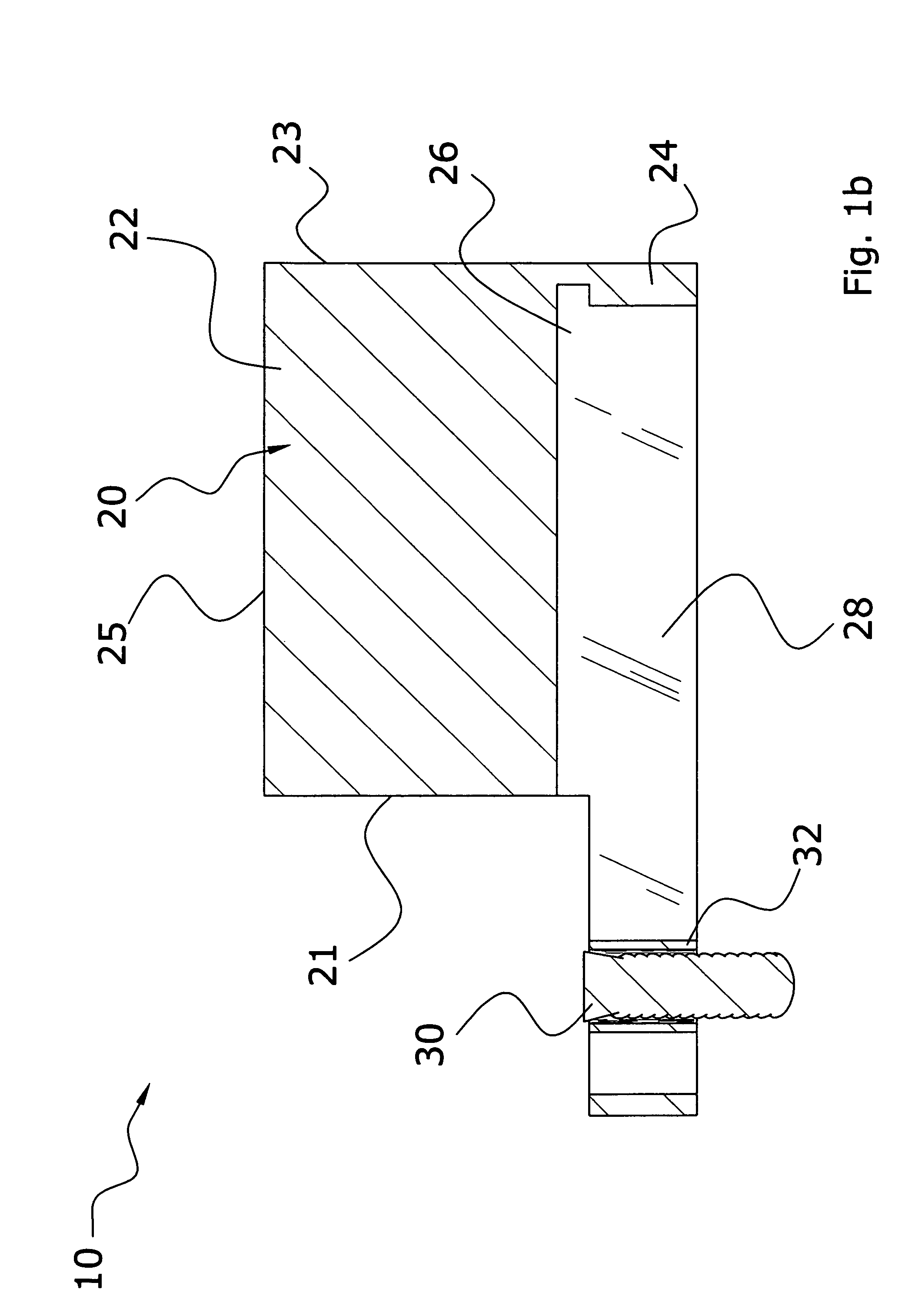
[0030]Turning now descriptively to the drawings, in which similar reference characters denote similar elements throughout the several views, FIGS. 1a through 4 illustrate a lock guard system 10, which comprises a stop member 20 comprised of a base 22 including a upper slot 26 and a plate 24 that includes a lower slot 28 for receiving a fastener 30 and sleeve 32. The stop member 20 connects to an existing dead bolt mechanism by extending the fastener 30 and sleeve 32 through the lower slot 28 into an existing aperture in a covering plate 17. The stop member 20 is able to adjust about the sleeve 32 and lower slot 28 to allow the dead bolt mechanism to operate both normally or to prevent the knob 12 that controls the dead bolt from rotating.

B. Stop Member

[0031]The stop member 20 is preferably made of a rigid material that will not distort when a fastener 30 is attached or when the knob 12 of the dead bolt mechanism comes in contact. The stop member 20 is preferably made of a...


PUM


Abstract

A lock guard system for efficiently securing a dead bolt lock mechanism from outside access. The lock guard system includes a stop member comprised of a base including an upper slot and a plate that includes a lower slot for receiving a sleeve and fastener. The stop member connects to an existing dead bolt mechanism by extending the fastener and sleeve through the lower slot into an existing aperture in a covering plate. The stop member is able to adjust about the sleeve and lower slot to allow the dead bolt mechanism to operate both normally or to prevent the knob that controls the dead bolt from rotating.

Description

CROSS REFERENCE TO RELATED APPLICATIONS[0001]Not applicable to this application.STATEMENT REGARDING FEDERALLY SPONSORED RESEARCH OR DEVELOPMENT[0002]Not applicable to this application.BACKGROUND OF THE INVENTION[0003]1. Field of the Invention[0004]The present invention relates generally to door lock devices and more specifically it relates to a lock guard system for efficiently securing a dead bolt lock mechanism from outside access.[0005]2. Description of the Related Art[0006]Any discussion of the prior art throughout the specification should in no way be considered as an admission that such prior art is widely known or forms part of common general knowledge in the field.[0007]Door lock devices have been in use for years. Typically, door locks and more specifically dead bolts are accessible from both sides of a door. Usually the inside of the door has a knob for controlling the extension and retraction of the dead bolt while the outside of the door utilizes a key for controlling th...

Claims


Application Information

Patent Timeline
Patent Type & Authority Patents(United States)
IPC IPC(8): E05B13/04
CPCE05B13/002Y10T70/7989Y10T70/5774Y10T292/1028Y10T70/7915
Inventor NOKLEBERG, ALBERT J.
Owner NOKLEBERG ALBERT J
Learn More