
Method and apparatus for streaming force values to a force feedback device

a technology of force feedback and interface device, which is applied in the direction of mechanical control device, manual control with single controlling member, instruments, etc., can solve the problems of large and heavy actuators, large size, weight, and power consumption of actuators, and achieve the effect of less complex forces and minimal reduction in the realism of generated forces

Inactive Publication Date: 2007-04-24
IMMERSION CORPORATION
View PDF247 Cites 96 Cited by
  • Summary
  • Abstract
  • Description
  • Claims
  • Application Information

AI Technical Summary

Benefits of technology

The present invention provides a method for generating force signals for creating feel sensations on a user through a force feedback device. The force signals are generated using an impulse-shaped waveform that reduces the necessary force output from the actuators, resulting in smaller, less complex forces with minimal reduction in realism. The force signals are generated based on control parameters and impulse parameters, and can be used to create realistic sensations of constant force without having to continuously output a high magnitude force. The invention also includes a method for generating "condition" forces and "effect" forces for creating feel sensations, as well as a method for transmitting force signal data in a force feedback system. The invention advantageously manipulates only those variables of the force signal that have a significant impact on the user's perception, reducing the complexity of the required hardware and minimizing the computational burden. Overall, the invention provides a low-cost force feedback device that can provide accurate and realistic force feedback for the mass market of home computer systems.

Problems solved by technology

This is because most of the force feedback devices have been targeted at the specific needs of highly industrial applications, and not a mass consumer market.
One consumer market design concern that is always present in force feedback devices is the size, weight, and power consumption of actuators included in the device.
However, in the consumer market, such large and heavy actuators are a major drawback, since consumers would prefer a portable, small interface device that can easily fit on a desktop or other small working space.
Even more significantly, such large actuators prevent producing a force feedback interface device at a low enough cost to be acceptable to mass market consumers.
In the prior art, however, smaller actuators were not an option if realistic forces were to be presented to the user.
However, force feedback devices with small actuators have a problem in that they may not allow the superposition of many types of force effects due to a limited dynamic range available from the actuators.
For example, the jolt sensation would have to be reduced in magnitude, thus reducing the effectiveness of that feel sensation to the user.
Providing actuators with a greater dynamic range typically means providing larger, more expensive actuators, which is not usually feasible in the consumer market as explained above.
In addition, there is unnecessary complexity in the manipulation of force feedback signals in the prior art.
However, the computational burden of providing feel sensations to a user can be high, especially when providing multiple simultaneous feel sensations.
To adequately provide the desired forces, complex and expensive components typically must be included in the force feedback device, often pushing the cost of realistic force feedback out of the reach of mass market consumers.

Method used


Image

  • Method and apparatus for streaming force values to a force feedback device
  • Method and apparatus for streaming force values to a force feedback device
  • Method and apparatus for streaming force values to a force feedback device

Examples


Embodiment Construction

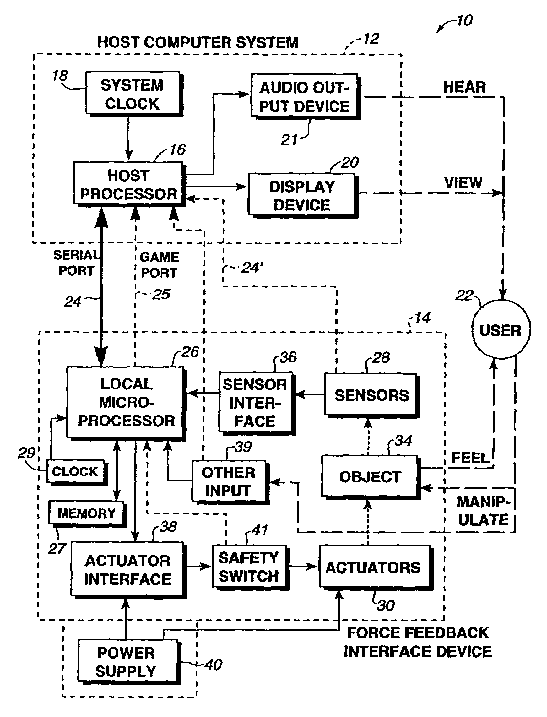
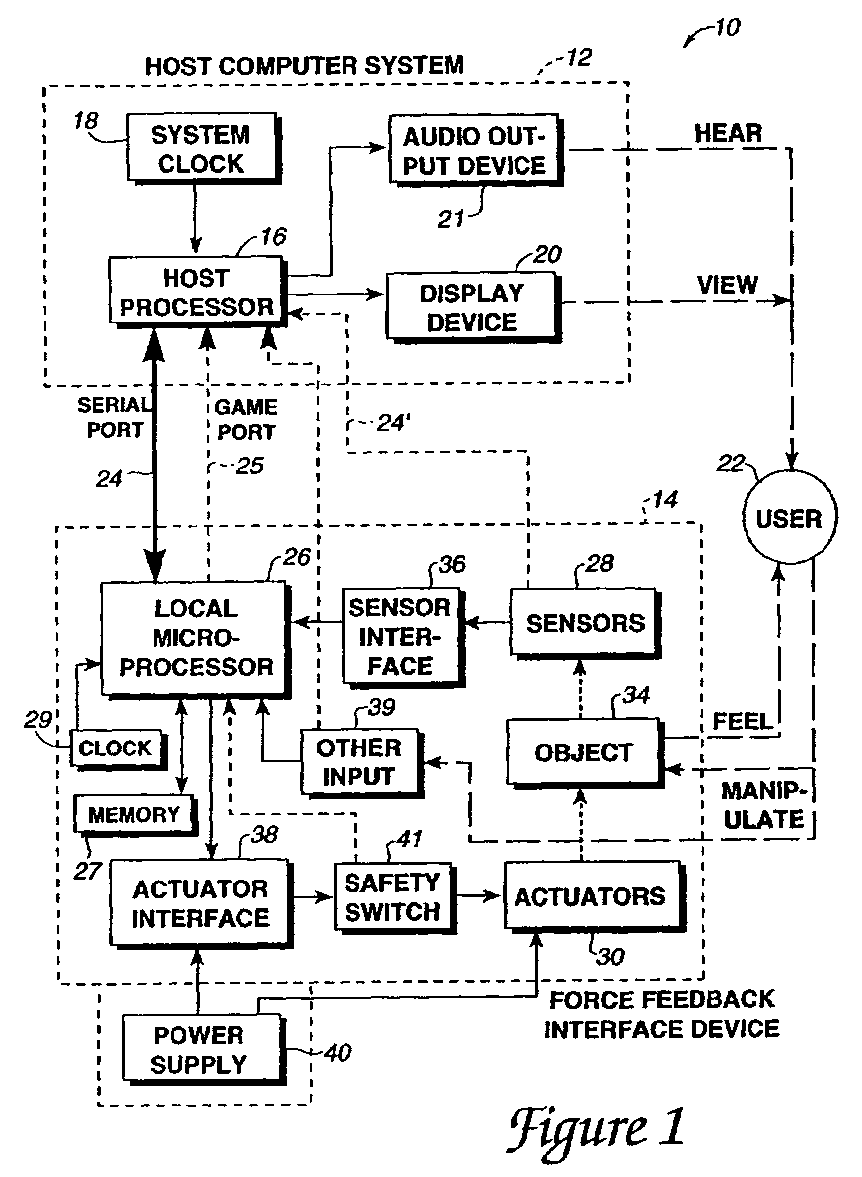
[0029]FIG. 1 is a block diagram illustrating an interface system 10 of the present invention for a force feedback interface device controlled by a host computer system. Interface system 10 includes a host computer system 12 and an interface device 14.

[0030]Host computer system 12 is preferably a personal computer, such as an IBM-compatible or Macintosh personal computer, or a workstation, such as a SUN or Silicon Graphics workstation. For example, the host computer system can a personal computer which operates under the MS-DOS or Windows operating systems in conformance with an IBM PC AT standard. Alternatively, host computer system 12 can be one of a variety of home video game systems commonly connected to a television set, such as systems available from Nintendo, Sega, or Sony. In other embodiments, home computer system 12 can be a television “set top box” or a “network computer” which can be used, for example, to provide interactive computer functions to users over networks.

[0031...


PUM


Abstract

A method and apparatus for shaping force signals for a force feedback device. A source wave is provided and is defined by a set of control parameters (including a steady state magnitude, a frequency value and a duration value) and modified by a set of impulse parameters (including an impulse magnitude, and a settle time representing a time required for the impulse magnitude to change to the steady-state magnitude). Optionally, application parameters specifying a direction of force signal and trigger parameters specifying activating buttons can also be provided for the source wave. Using a host processor or a local processor, the force signal is formed from the source wave and the sets of control parameters and impulse parameters, where the force signal includes an impulse signal followed by a continual steady-state signal after an expiration of the settle time. A feel sensation is generated to a user of the force feedback device as physical forces produced by actuators on the force feedback device in response to the force signal. The steady-state magnitude value is lower than a magnitude value of a non-impulse-shaped force signal required to create a corresponding feel sensation having a similar apparent sensation to the user.

Description

CROSS REFERENCE TO RELATED APPLICATIONS[0001]This is a continuation application of prior U.S. application Ser. No. 09 / 618,966, filed on Jul. 19, 2000, now U.S. Pat. No. 6,661,403; which is a divisional of prior U.S. application Ser. No. 09 / 322,245, filed on May 28, 1999, now U.S. Pat. No. 6,278,439; which is a continuation of prior U.S. application Ser. No. 08 / 747,841, filed on Nov. 13, 1996, now U.S. Pat. No. 5,959,613; which is a continuation-in-part of prior U.S. application Ser. No. 08 / 566,282, filed on Dec. 1, 1995, now U.S. Pat. No. 5,734,373; and all of which are incorporated herein by reference.BACKGROUND OF THE INVENTION[0002]The present invention relates generally to interface devices between humans and computers, and more particularly to computer interface devices that provide force feedback to the user.[0003]Computer systems are used extensively in many different industries to implement computer controlled simulations, games, and other application programs. More particul...

Claims


Application Information

Patent Timeline
Patent Type & Authority Patents(United States)
IPC IPC(8): G09G5/00A63F13/06G05G9/047G06F3/00G06F3/01G06F3/038H04L29/06
CPCA63F13/06G05G9/047G06F3/016G06F3/0383G06F3/011A63F2300/1025A63F2300/1037G05G2009/04766G05G2009/04777H04L67/38G06F2203/014G06F2203/015H01H2003/008H04L67/131A63F13/285A63F13/23A63F13/21
Inventor ROSENBERG, LOUIS B.BRAUN, ADAM C.
Owner IMMERSION CORPORATION
Learn More