
Speckle based sensor for three dimensional navigation

a technology of three-dimensional navigation and speckle based sensors, applied in navigation instruments, instruments for comonautical navigation, distance measurement, etc., can solve the problems of multiple optical components, low collection efficiency of speckle based sensors, and relatively complex approach

Active Publication Date: 2007-04-17
PIXART IMAGING INC
View PDF5 Cites 34 Cited by
  • Summary
  • Abstract
  • Description
  • Claims
  • Application Information

AI Technical Summary

Benefits of technology

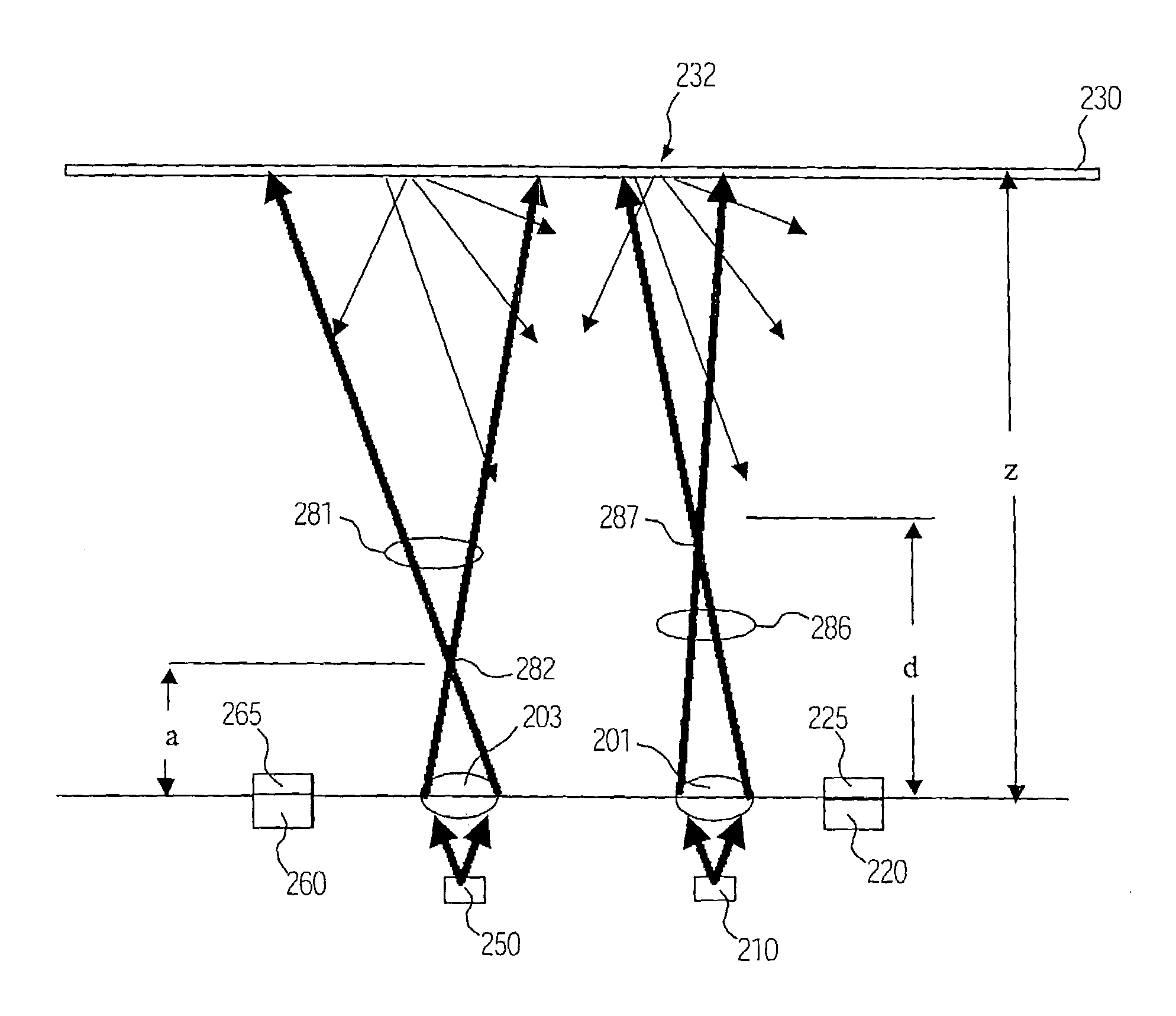
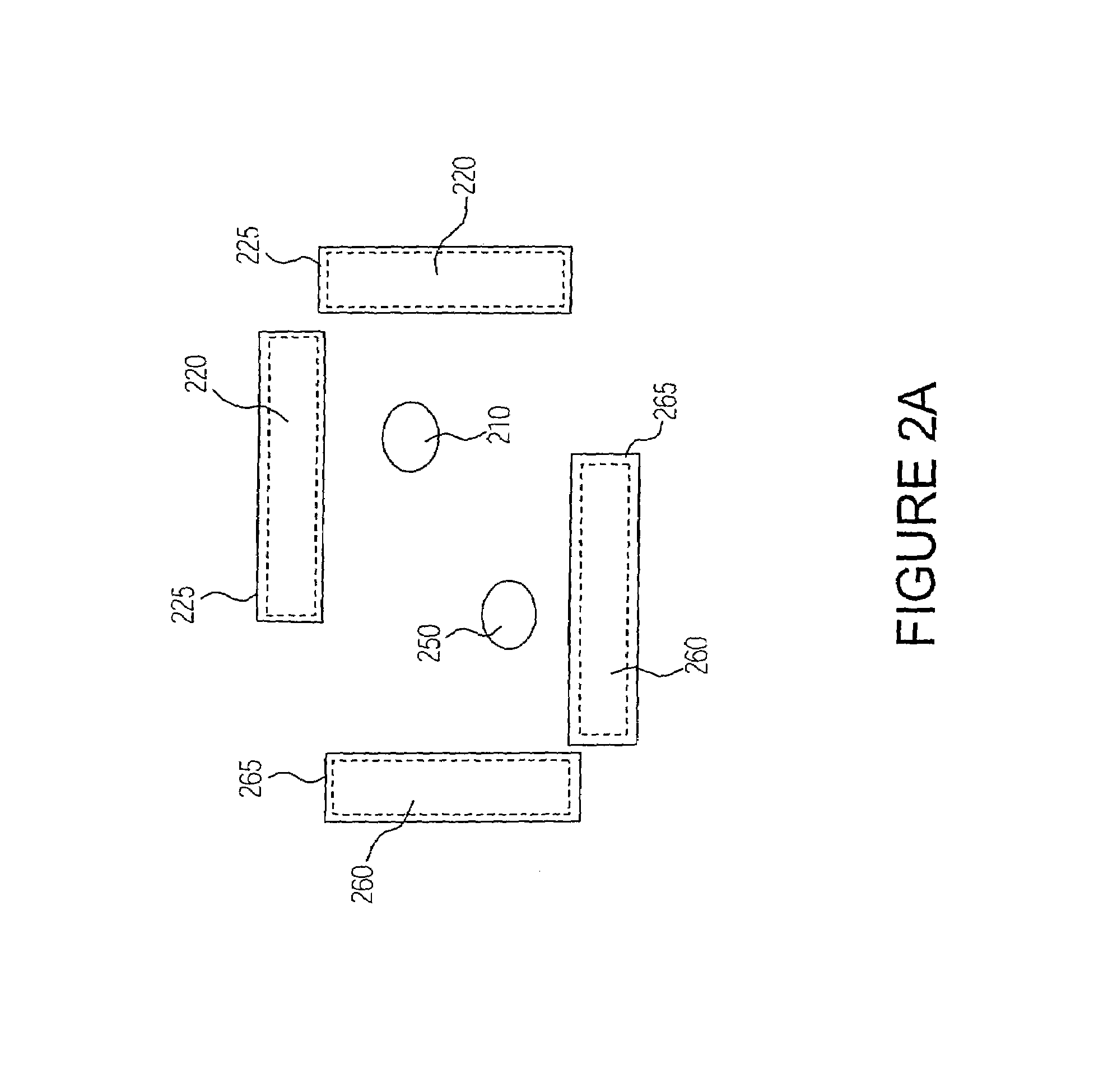
The invention describes a way to navigate in three dimensions using a speckle pattern. This pattern is not dependent on the surface being walked on, and can be achieved using two coherent sources or one appropriately filtered. The use of speckle motion allows for optical navigation that is largely independent of the surface characteristics. Additionally, non-speckle optical navigation methods can also be used for two-dimensional surface navigation, with speckle being used only for navigation in the third dimension.

Problems solved by technology

Hence, sensors in speckle based navigation typically suffer from low collection efficiency.
However, the second approach is relatively involved and typically requires multiple optical components.

Method used


Image

  • Speckle based sensor for three dimensional navigation
  • Speckle based sensor for three dimensional navigation
  • Speckle based sensor for three dimensional navigation

Examples


Embodiment Construction

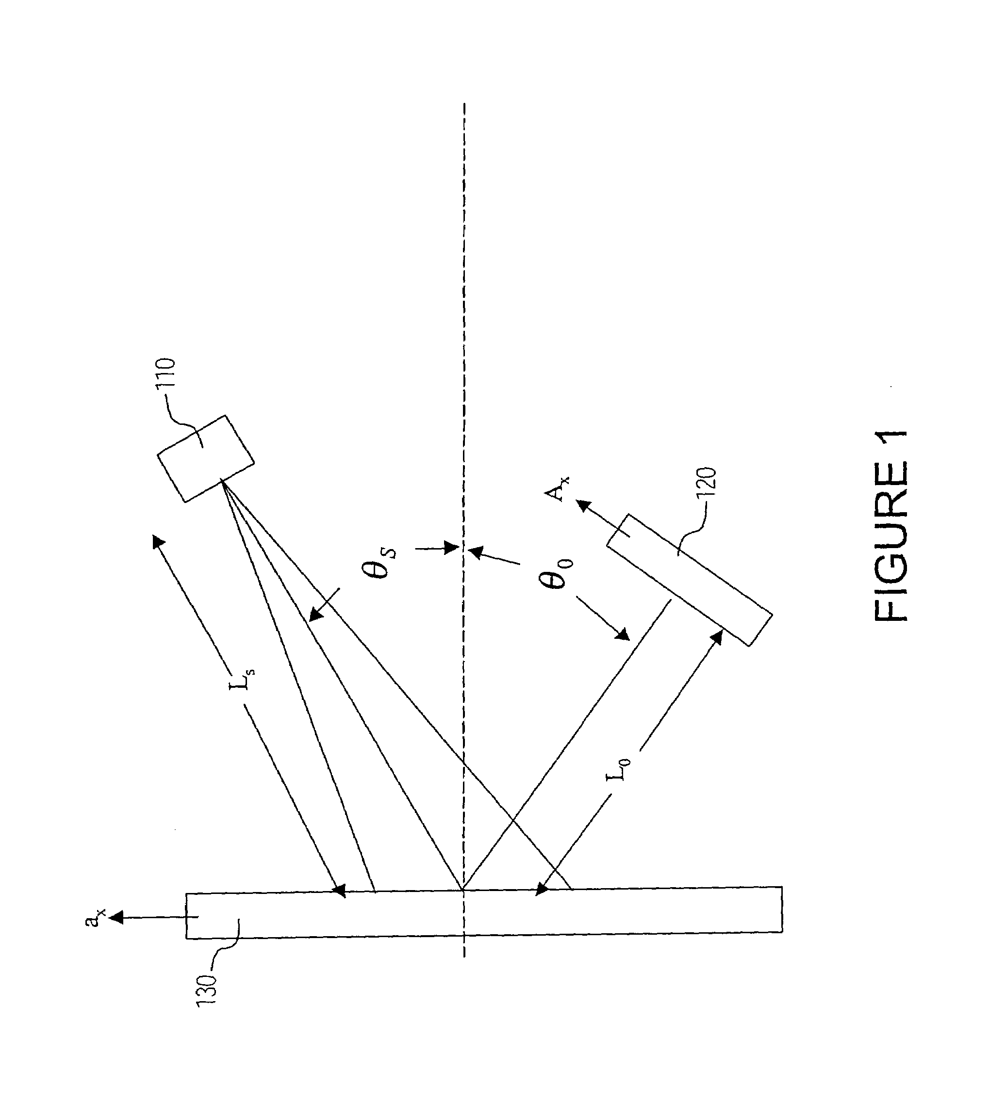
[0019]FIG. 1 illustrates the geometry involved with a typical speckle navigation sensor. Laser 110 illuminates target surface 130 which creates a speckle pattern that is imaged at detector 120. The radius of curvature of the laser wavefronts from laser 110 incident on target surface 130 is LS. If the light hitting target surface 130 is collimated, the wavefront is planar and LS is infinite. The speckle pattern originating from target surface 130 and being imaged at detector 120 travels a distance L0. If the angles of incidence and speckle emission are θS and θ0, respectively, then a displacement relative to the target equal to ax causes a displacement of the speckle pattern at detector 120 equal to Ax. Ax and ax are related to each other by the following expression:

[0020]Ax=ax⁢{L0⁢cos2⁢θSLS⁢cos⁢⁢θ0+cos⁢⁢θ0}(1)

where only motion in the x direction in the x-y plane is considered in the derivation without loss of generality. For motion in the y direction in the x-y plane the expression ...


PUM


Abstract

Motion of a speckle pattern is employed to provide for navigation in three dimensions. Non-speckle optical navigation methods may also be used to provide for two dimensional surface navigation with speckle being used to provide for navigation in the third dimension.

Description

CROSS REFERENCE TO RELATED APPLICATIONS [0001]This application is related to the patent application entitled “METHOD AND APPARATUS FOR IMPROVED COLLECTION EFFICIENCY OF SPECKLE BASED NAVIGATION SENSORS USING LIGHTPIPES AND REFLECTORS” Ser. No. 10 / 632,619 filed on the same day and assigned to the same assignee.FIELD OF INVENTION [0002]This invention relates to optical navigation devices in three dimensions such as those used with computers.BACKGROUND OF INVENTION [0003]Speckle patterns are created when coherent light is reflected from a target surface. If the target surface or coherent light source moves laterally, the associated speckle pattern also moves. This provides the operational basis for speckle based navigation systems. Typically, these speckle based navigation systems involve navigation in two dimensions, see for example, Schnell, Piot and Daendliker, “Detection of movement with laser speckle patterns: statistical properties”, JOSA A, vol. 15, 1, pp. 207–216, 1998. Speckle...

Claims


Application Information

Patent Timeline
Patent Type & Authority Patents(United States)
IPC IPC(8): G01C21/00G01B11/26G01C1/00G01C3/00G01C3/08G01C5/00G01P3/36G01S17/50G01S17/87G06F3/033G06F3/042G06M7/00H01J40/14
CPCG01P3/36G01S17/50G01S17/87G06F3/0346G06F3/0421
Inventor GRUHLKE, RUSSELL W.DLAZ, DENNIS C.
Owner PIXART IMAGING INC
Learn More