
Welding tip

a technology of welding tip and tip, which is applied in the direction of soldering apparatus, press ram,auxillary welding device, etc., can solve the problems of burning or cutting of vents, difficult welding of polymeric materials such as ptfe to high or low density plastic caps or plugs, etc., to prevent accidental burning or cutting, and improve the welding of vents.

Inactive Publication Date: 2007-04-17
RIEKE
View PDF31 Cites 3 Cited by
  • Summary
  • Abstract
  • Description
  • Claims
  • Application Information

AI Technical Summary

Benefits of technology

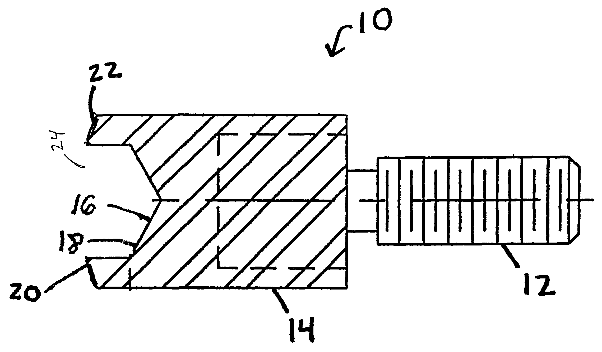
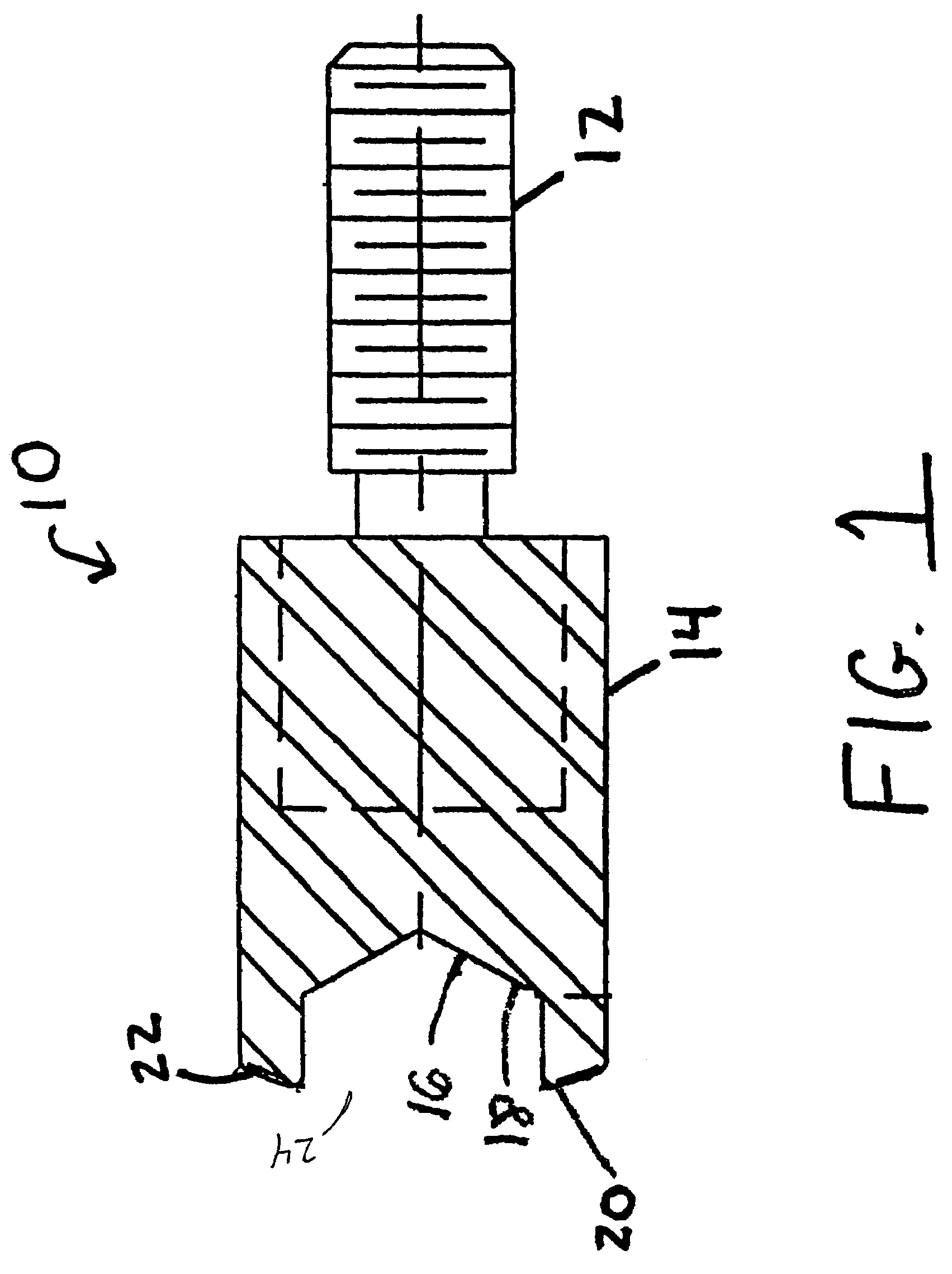
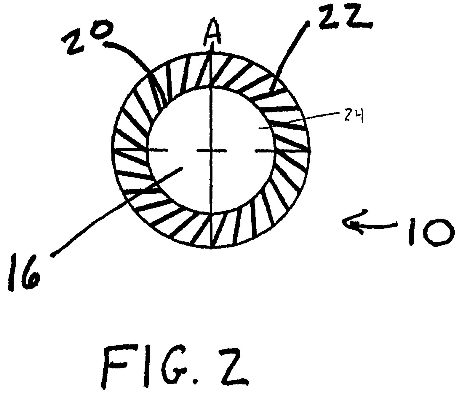
[0005]The present invention is directed to a welding tip that improves the welding of a vent formed from a polymeric material such as PTFE onto plastic such as a plastic cap or plug. The improved welding tip utilizes a shape and structure that provides variable pressure and heat to the polymeric material vent. The variable heat and pressure provide a more controlled melt to the vent to prevent accidental burning or cutting. When the welding tip is applied onto the polymeric material vent placed over the cap or plug, the plastic cap or plug melts and penetrates into the vent to secure the vent to the cap or plug. It has been found that welding tip features such as pressure, temperature, and shape help produce a desirable weld between the polymeric material vent and the plastic cap. The welding tip welds the vent without burning or cutting the vent material.

Problems solved by technology

Vents formed from polymeric material such as PTFE are difficult to weld to high or low density plastic caps or plugs.
Particularly, welding the vent from such polymeric material may cause burning or cutting of the vent.

Method used


Image

  • Welding tip
  • Welding tip
  • Welding tip

Examples


Embodiment Construction

[0011]Referring now to the drawings wherein the drawings are for the purposes of illustrating the preferred embodiment of the invention only and not for purposes of limiting same, FIG. 1 shows a welding tip 10. The welding tip 10 includes a threaded bolt 12 that is attachable to a weld gun. The welding tip 10 also includes a body 14 connected to the threaded bolt 12. The body 14 is cylindrical-shaped although other geometric shapes are also contemplated. Also, the body 14 is metal although other materials are also contemplated. The body 14 defines a central bore 16 along its interior wall 18. The central bore 16 is conical-shaped although other geometric shapes are contemplated. A perimeter 20 is located at an end of the body 14. The perimeter 20 is ring-shaped and defines an opening 24 at the end of the body 14. The perimeter 20 is angled or tapered from its inner portion to its outer portion so that the inner portion of the perimeter 20 extends longitudinally outward further than ...


PUM

PropertyMeasurementUnit
perimeteraaaaaaaaaa
temperatureaaaaaaaaaa
conical shapeaaaaaaaaaa

Abstract

The present invention is directed to a welding tip for welding polymeric materials such as containers. The welding tip includes a cylindrical body. The cylindrical body defines a central bore and includes a perimeter around the bore. The perimeter includes one or more knurls. The knurls provide the welding tip with varying temperatures and pressure points to create a more desirable weld.

Description

CROSS-REFERENCE TO RELATED APPLICATIONS[0001]This application is related to, and claims all benefits of U.S. Provisional Patent Application Ser. No. 60 / 423,081, filed on Nov. 1, 2002.FIELD OF THE INVENTION[0002]The present invention relates to a welding tip for the welding of plastic and plastic containers.BACKGROUND OF THE INVENTION[0003]Within the art of plastic containers for transporting liquids, solids, etc., such as plastic 55-gallon containers, vents typically must be installed in the container to assist in venting gases that can build up inside and cause failure of a cap or plug on the container or the container itself. Generally, caps or plugs are installed in the containers to help prevent such failure. The caps or plugs are drilled to provide a center aperture therethrough to provide communication between the container interior and the external environment. Such center apertures are covered by vents that permit gases, but not liquids, to be released from the container. Ty...

Claims


Application Information

Patent Timeline
Patent Type & Authority Patents(United States)
IPC IPC(8): B32B37/00B23KB23K3/00B29C65/00B29C65/02B29C65/18B30B1/00B65D51/16
CPCB29C65/02B29C66/534B29C66/80B29C66/81431B29C66/8167B29C66/81427B29C66/24221B29C66/81415B29C65/00B29C66/71B29C66/81435B29C66/006B29K2027/18
Inventor HICKMAN, JOHNNY M.MYERS, MARK A.TAYLOR, DALE W.
Owner RIEKE
Learn More