Ergonomic systems and methods providing intelligent adaptive surfaces
a technology of adaptive surfaces and ergonomics, applied in the field of ergonomic systems, can solve the problems of increasing contact patches and medical problems, and achieve the effects of reducing the actual recovery time and related medical costs of individuals, limiting or preventing subsequent and often costly future complications, and reducing lost productivity tim
- Summary
- Abstract
- Description
- Claims
- Application Information
AI Technical Summary
Benefits of technology
Problems solved by technology
Method used
Image
Examples
example 1
Cryotherapy System External Canister
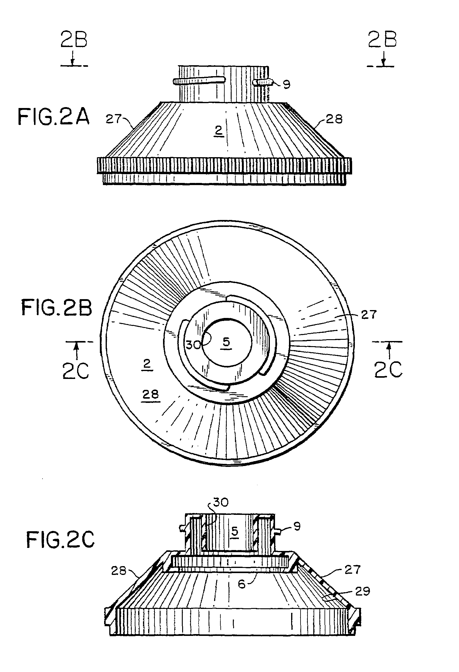
[0331]A disposable canister 1 is provided with an adapter 2, which is designed to operate in conjunction with the inject valve 3. The adapter 2 fits atop a standard-type aerosol can, providing access to the standard valve stem 4 via a deep narrow recess 5 to prevent accidental or intentional misuse. The adapter 2 also allows stacking of the canisters. The canister adapter 2 has an undercut lip 6 to hold on to the edge of the coolant canister dispensing valve. The adapter 2 is designed for one time use, or it may be reused on a new or recharged canister 1. When the undercut lip 6 snaps over a portion of the valve cap 8, it is distorted into a positive lock through a full revolution. Thus, after mounting on the canister 1, the adapter 2 is rotationally stable with respect to the axis of the canister 1, while remaining securely in place. On the outside of the adapter 2 is a ½ turn interrupted helical thread 9 that provides a positive lock when the in...
example 2
Cryotherapy System Inject Valve
[0335]The inject valve 3 according to the present invention mates to the canister adapter 2, providing a sealed path from the canister valve 15, through the inject valve 3, to a piece of tube 24 which connects the inject valve 3 to the heat transfer portion of the cryotherapy device 16. Thus, the inject valve body 31 mates to the ½ turn interrupted screw thread 9, and connects easily. The ½ turn thread 9 causes the inject valve 3 to move axially toward the canister 1, and locks in place. The inject valve 3 includes a hollow cylindrical central post 12 which protrudes downward, concentric and outside the valve stem 4 of the canister 1. The stem or central cylindrical post 12 of the inject valve 3 depresses the valve stem 4 of the canister 1, releasing its contents, the refrigerant 13. An O-ring 14 provides a seal so that the refrigerant 13 does not leak around the inject valve 3.
[0336]The inject valve 3 comprises two flow paths. A first flow path provid...
example 3
Cryotherapy System Overcap
[0339]An overcap 35 is preferably provided to prevent the inject valve pushbutton 22 from becoming lost. The overcap 35 is sealed to the inject valve body 31 by means of ultrasonic welding. The overcap 35 also includes a “V” type clip 36 which fits over the umbilical tube 24 which carries the refrigerant 13 from the inject valve 3 to the cryotherapy device 16, thereby preventing accidental disconnection of the tube 24. The retaining structure including the “V” type clip 36 also prevents catastrophic results from a kink in the tube 24 by ensuring that the flow path does not fail if the flow is temporarily blocked. The tube 24 is preferably a ⅛″ ID Tygon® or polyurethane tube, which is inserted around a hollow stem 37 protruding from the side of the inject valve body 31.
PUM
 Abstract
Description
Claims
Application Information
 - R&D
- Intellectual Property
- Life Sciences
- Materials
- Tech Scout
- Unparalleled Data Quality
- Higher Quality Content
- 60% Fewer Hallucinations
Browse by: Latest US Patents, China's latest patents, Technical Efficacy Thesaurus, Application Domain, Technology Topic, Popular Technical Reports.
© 2025 PatSnap. All rights reserved.Legal|Privacy policy|Modern Slavery Act Transparency Statement|Sitemap|About US| Contact US: help@patsnap.com


