
Artificial intervertebral disc replacements incorporating reinforced wall sections

a technology of intervertebral discs and reinforced wall sections, which is applied in the field of artificial intervertebral disc replacement apparatuses, can solve the problems of reduced treatment effect of disc degeneration, and reduced efficiency of disc degeneration surgery, so as to facilitate load transfer

Inactive Publication Date: 2007-04-10
ANOVA
View PDF108 Cites 61 Cited by
  • Summary
  • Abstract
  • Description
  • Claims
  • Application Information

AI Technical Summary

Benefits of technology

[0016]To enhance strength or longevity, the body may further include the use of fiber-reinforced materials on one or more outer surfaces or wall structures, as the case may be. Similar to commercial tire construction, such fiber-reinforced materials may be of a bias-ply, radial-ply or bias-belted construction. One configuration include an outer compressible member peripherally attached to a central “hub,” similar, at least in concept, to the which a tire is mounted onto a wheel.
[0018]The preferred embodiments accordingly dispense with a central hub, and the “belt” is limited to a portion of the outer wall of the body. The body of the device and / or a portion of the outer wall is fortified, reinforced, stiffened or otherwise strengthened with a higher durometer, for example, where it rests against a weakened or deficient area of the annulus fibrosus (AF). The “less stiff” portions facilitate the transfer of load to the healthier portion of the AF.

Problems solved by technology

The nucleus becomes thinner and less able to handle compression loads.
The redundant annular fibers are less effective in controlling vertebral motion.
Current surgical treatments of disc degeneration are destructive.
These destructive procedures lead to acceleration of disc degeneration.
The first two groups of procedures compromise the treated disc.
The additional stress results in premature disc degeneration of the adjacent discs.

Method used


Image

  • Artificial intervertebral disc replacements incorporating reinforced wall sections
  • Artificial intervertebral disc replacements incorporating reinforced wall sections
  • Artificial intervertebral disc replacements incorporating reinforced wall sections

Examples


Embodiment Construction

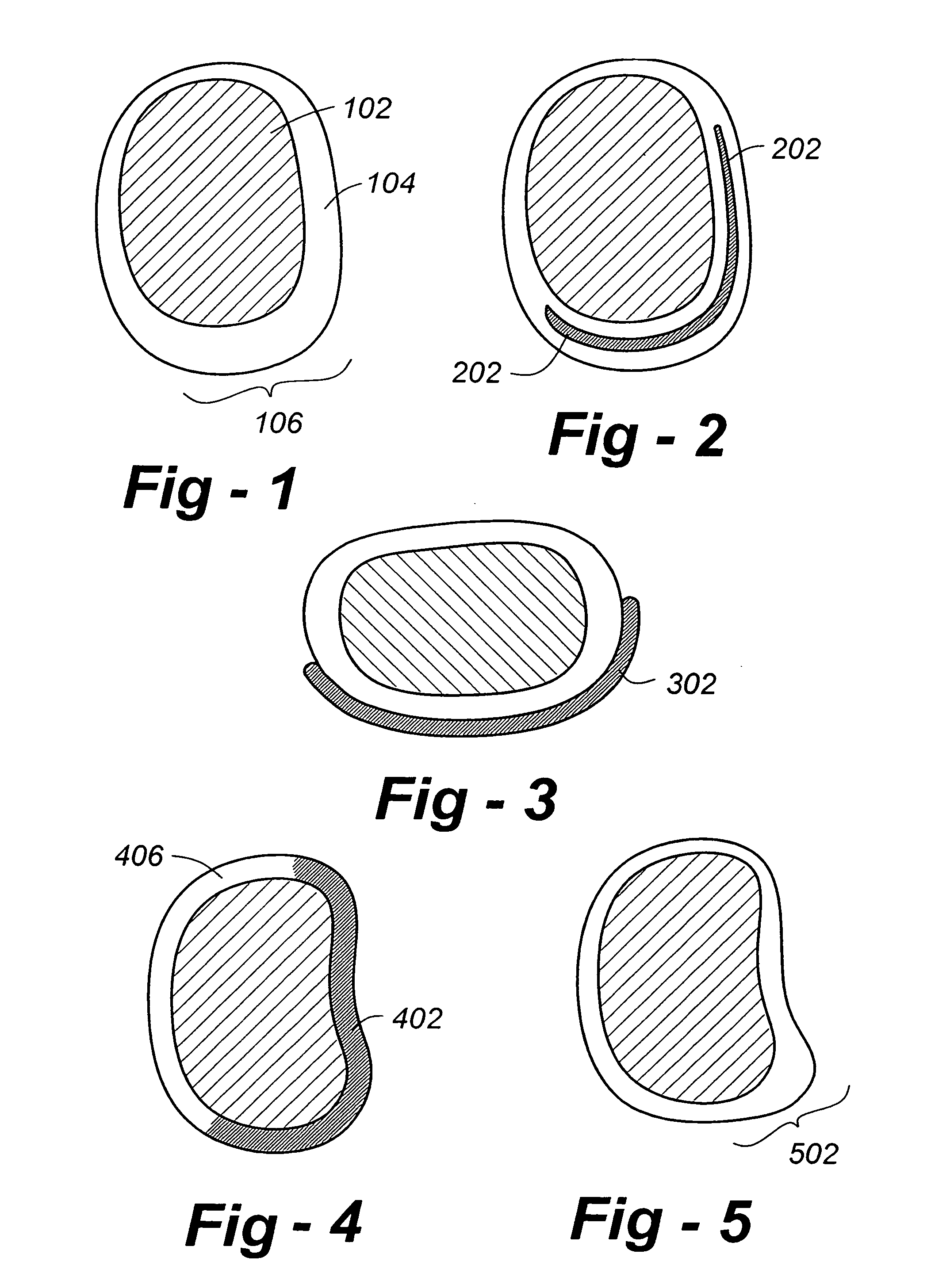
[0036]Turning now to the various drawings, FIG. 1 is an axial cross section through an ADR constructed in accordance with this invention. Area 102 represents a compressible or resilient cushioning material, such as, hydrogel, polyurethane, or other polymer, including elastomers. The outer wall 104 of the ADR includes one or more areas with increased radial stiffness. For example, note that the portion 106 of the wall in this case is intentionally thickened to increase the radial stiffness of that portion.

[0037]In addition to thickening a portion of the wall, a different material may be used, provided either through bonding or through a change in composition. Alternatively, a material may be used that is strengthened, fortified, reinforced or otherwise stiffened through the application of energy or a chemical. For example, ultraviolet light or another form of radiation may be used to locally stiffen a section of the wall, as would be the case with certain types of polymerization tech...


PUM

PropertyMeasurementUnit
Forceaaaaaaaaaa
Pressureaaaaaaaaaa
Volumeaaaaaaaaaa

Abstract

An Artificial Disc Replacement (ADR) includes a body and / or outer wall that is fortified, reinforced, stiffened or otherwise strengthened with a higher durometer, for example, where it rests against a weakened or deficient area of the annulus fibrosis (AF). The “less stiff” portions facilitate the transfer of load to the healthier portion of the AF. A hydrogel or other compressible and / or resilient material may be used within the center of the ADR to selectively transfer the forces to the outer wall. The outer wall may constructed of an elastomer, and may include a radial ply, bias ply, and / or belted construction. Methods of determining a properly sized ADR are also disclosed.

Description

REFERENCE TO RELATED APPLICATIONS[0001]This application is a continuation-in-part of U.S. patent application Ser. No. 10 / 303,385, filed Nov. 25, 2002; which is a continuation-in-part of U.S. patent application Ser. No. 10 / 191,639, filed Jul. 9, 2002 and Ser. No. 09 / 415,382, filed Oct. 8, 1999, now U.S. Pat. No. 6,419,704. The entire content of each application and patent is incorporated herein by reference.FIELD OF THE INVENTION[0002]This invention relates generally to surgical techniques and prosthetic components therefore and, in particular, to intervertebral disc replacement apparatus and methods of implanting the same.BACKGROUND OF THE INVENTION[0003]Eighty-five percent of the population will experience low back pain at some point. Fortunately, the majority of people recover from their back pain with a combination of benign neglect, rest, exercise, medication, physical therapy, or chiropractic care. A small percent of the population will suffer chronic low back pain. The cost of...

Claims


Application Information

Patent Timeline
IPC IPC(8): A61F2/06A61F2/00A61F2/30A61F2/44
CPCA61F2/441A61F2/442A61F2/30771A61F2/30965A61F2002/30133A61F2002/30331A61F2002/30383A61F2002/30462A61F2002/30584A61F2002/30828A61F2002/30841A61F2002/30879A61F2002/4435A61F2002/448A61F2220/0025A61F2220/0033A61F2220/0075A61F2230/0015A61F2310/00017A61L2430/38
Inventor FERREE, BRET A.
Owner ANOVA
Learn More