Fluid line connector with intermediate smooth surface

a technology of fluid line connector and smooth surface, which is applied in the direction of adjustable joints, branching pipes, mechanical equipment, etc., can solve the problems of significant cost associated with these types of arrangements, significant time and effort required to install the fitting on or through the bulkhead, and additional time and effort required to attach the two fluid line segments to the opposing ends of the fitting, etc., to achieve the desired simplicity of structure, avoid or minimize problems and difficulties encountered, and increase the effect of performance and reliability

Inactive Publication Date: 2007-04-03
DORMONT MFG
View PDF28 Cites 10 Cited by
  • Summary
  • Abstract
  • Description
  • Claims
  • Application Information

AI Technical Summary

Benefits of technology

[0010]In accordance with the present invention, a fluid line connector is provided that avoids or minimizes the problems and difficulties encountered in connection with fluid line connectors of the foregoing nature, while promoting an increase in performance and reliability, and maintaining a desired simplicity of structure, economy of manufacture and ease of installation.

Problems solved by technology

Such arrangements have numerous disadvantages, however.
One disadvantage is that a significant amount of time and effort can be required to install the fitting on or through the bulkhead, which often disadvantageously requires simultaneous activity along both sides of the same.
Furthermore, once the fitting has been installed, additional time and effort is typically needed to attach the two fluid line segments to the opposing ends of the fitting.
As such, significant cost can be associated with these types of arrangements.
This is especially true where access to one or both sides of the bulkhead is limited.
What's more, by the very nature of such arrangements, it is not possible to pre-assemble the same to take advantage of mass production efficiencies.
Also, another disadvantage is that the materials or construction of the wall or bulkhead can limit the type and style of connections that can be used to attach the fitting to the bulkhead and to connect the fluid line segments to the fitting.
By way of example, if a polymeric material is used to form a portion of a bulkhead, the use of brazed connections may not be practical, as the heat needed to form the brazed joints could deform or otherwise damage the polymeric wall.
Such arrangements, however, have disadvantages similar to those described above in that at least one of the end fittings need to be installed on the fluid line after it is passed through the opening in the bulkhead or wall.
Once again, the end fittings are each on a different side of the bulkhead or wall, and the assembly of the end fittings onto the fluid line can be more difficult and time consuming where limited access or clearance is found on one or both sides of the bulkhead.
As such, significant costs of assembly are often associated with these types of arrangements as well.
One disadvantage of such arrangements is that a relatively small diameter fluid line can be left extending through a relatively large opening in the bulkhead.
However, sealing between the bulkhead and the fluid line can be difficult where the fluid line is of a flexible, corrugated material, such as flexible metal fluid lines having annular or helical corrugations, for example.
In these cases, the variable exterior of the fluid line makes the fluid-tight seating of a grommet, gasket or other sealing member difficult to achieve.

Method used


Image

  • Fluid line connector with intermediate smooth surface
  • Fluid line connector with intermediate smooth surface
  • Fluid line connector with intermediate smooth surface

Examples


Embodiment Construction

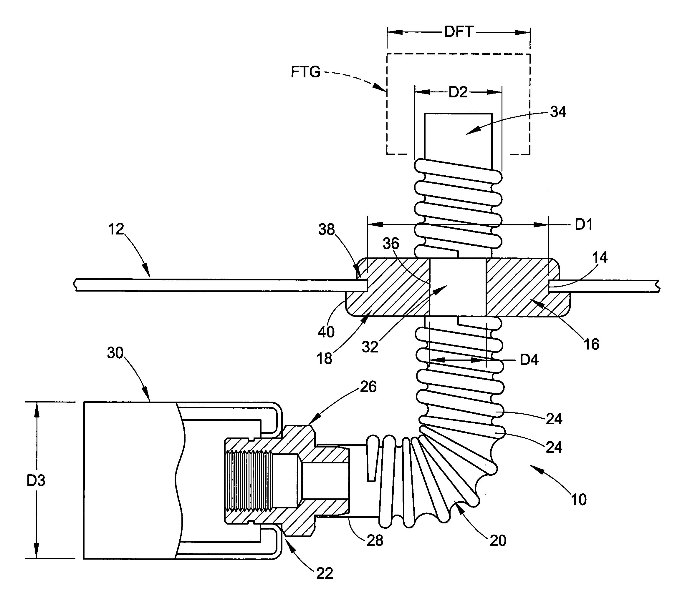
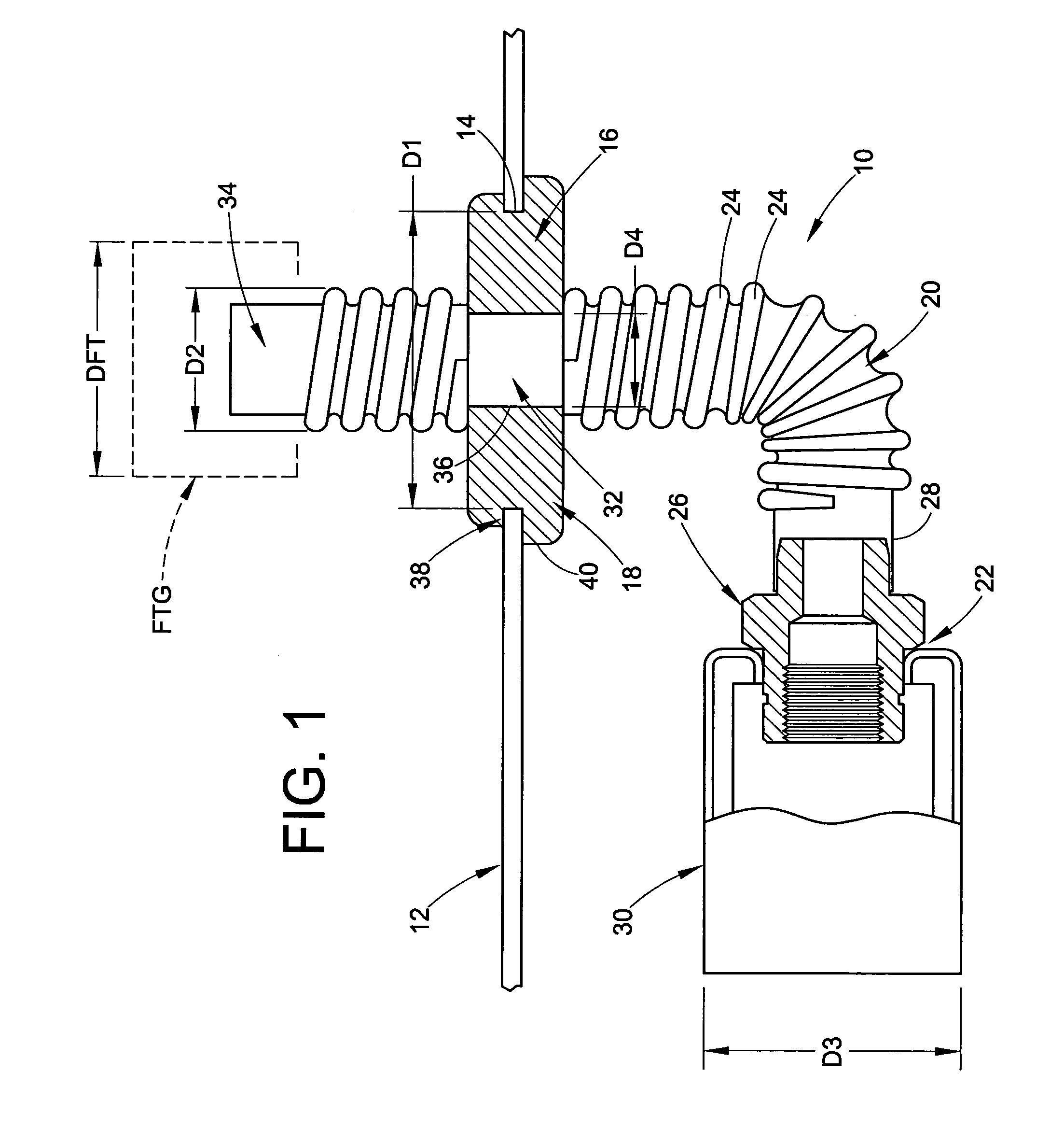
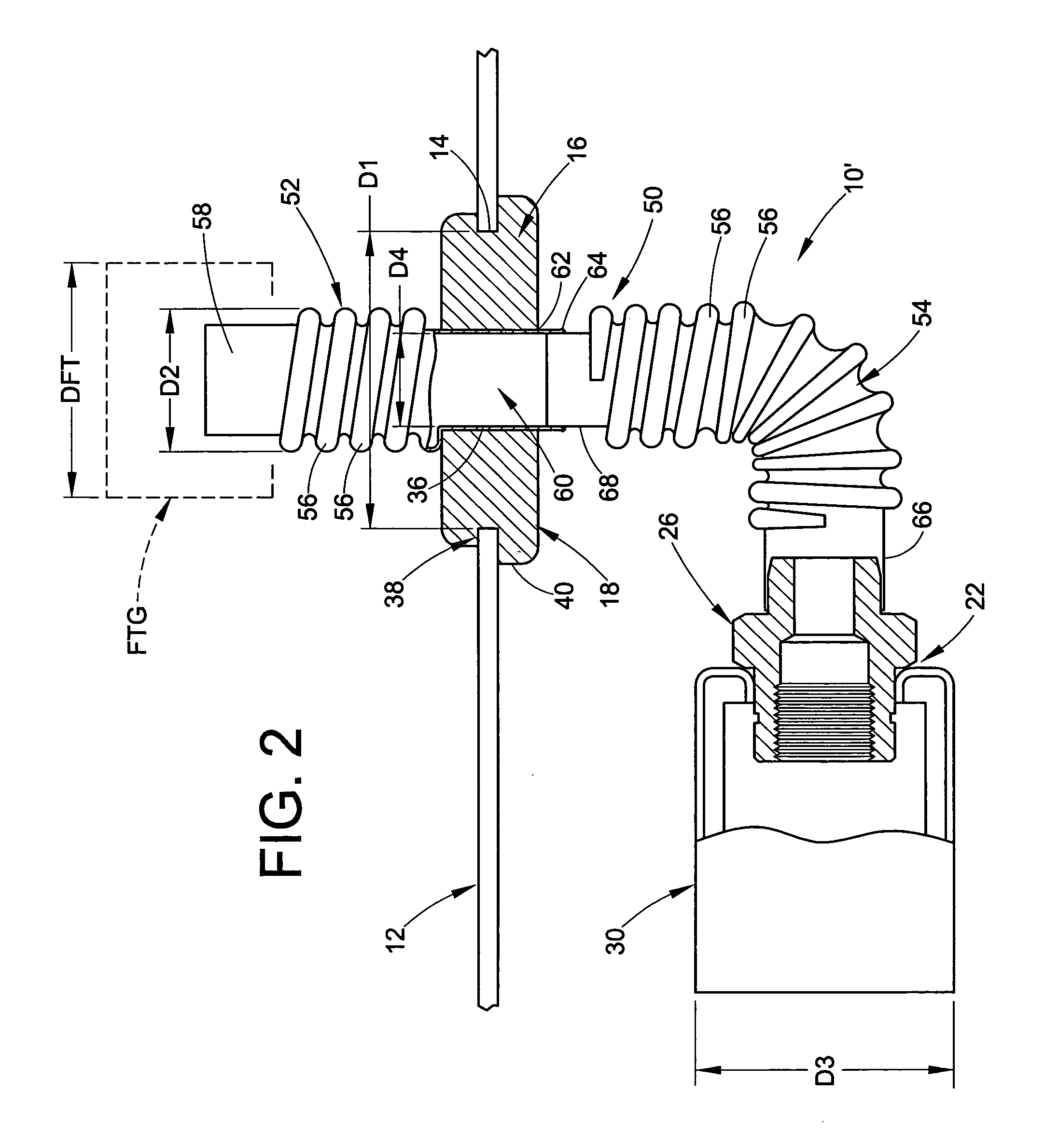
[0016]Referring now in greater detail to the drawings, wherein the showings are for the purposes of illustrating preferred embodiments of the invention only, and not for the purpose of limiting the invention, FIG. 1 shows a fluid line connector assembly 10 in accordance with the present invention installed on a wall or bulkhead 12. A passage wall 14 is provided on buikhead 12 that defines a hole or passage 16. Passage 16 has a maximum passage cross-sectional dimension D1, and can optionally include a minimum passage cross-sectional dimension (not shown) that is different than dimension D1.

[0017]Fluid line connector assembly 10 is supported on bulkhead 12 within passage 16 by a grommet or sealing member 18, and includes a length of flexible tubing 20 having an end fitting assembly 22 supported thereon. Preferably, flexible tubing 20 is a thin-walled, flexible, metal tubing having a plurality of corrugations 24 extending therealong. It will be appreciated that corrugations 24 are show...


PUM


Abstract

A fluid line connector includes a length of tubing having a plurality of corrugations formed therealong between opposing tubing ends. A non-corrugated section is disposed along the length of tubing between the opposing tubing ends such that a portion of the plurality of corrugations extends between the non-corrugated section and each of the opposing tubing ends.

Description

[0001]This application claims priority from U.S. Provisional Patent Application No. 60 / 474,176 filed on May 29, 2003, which is hereby incorporated herein by reference in its entirety.BACKGROUND[0002]This invention relates to the art of fluid line connectors and, more particularly, to corrugated fluid line connectors having an intermediate section with a smooth exterior that is suitable for use in forming a fluid-tight connection between the fluid line and a wall or bulkhead through which the fluid line extends.[0003]Fluid line connectors have been provided heretofore and are commonly known to extend and transport fluid through a wall or bulkhead, such as a firewall in the engine compartment of a vehicle or a firebox in a hearth application, for example. In many of such applications it is desirable to form a fluid-tight connection between the fluid line connector and the wall or bulkhead. This way, fluid on one side of the wall or bulkhead is not in fluid communication with the oppos...

Claims


Application Information

Patent Timeline
Patent Type & Authority Patents(United States)
IPC IPC(8): F16L5/02F16L5/10F16L11/15
CPCF16L5/10F16L11/15Y10S285/903
Inventor ANGUS, MICHAEL T.
Owner DORMONT MFG
Why Eureka
Try Eureka