Combination shut-off and resetable excess flow valve

Active Publication Date: 2005-02-03
ELSTER PERFECTION CORP
View PDF9 Cites 9 Cited by
  • Summary
  • Abstract
  • Description
  • Claims
  • Application Information

AI Technical Summary

Benefits of technology

[0008] In accordance with the present invention, a combination shut-off and resetable excess flow valve is provided that avoids or minimizes the problems and difficulties encountered with valves of the foregoing nature, while providing improved operation, and maintaining a desired simplicity of structure and economy of manufacture.

Problems solved by technology

Typically, the excess flow valve is buried in the ground and is not accessible without excavation.
While both types of excess flow valve have been successfully used for a considerable period of time, certain disadvantages have been perceived that have reduced the adoption and wide spread installation of excess flow valves.
One of the primary perceived disadvantages is that there is no external indicator of the condition (i.e., open or closed position) of an installed excess flow valve.
One significant disadvantage of such valves, however, is that if the valve is left in the third, resetting position, the excess flow valve will remain open regardless of the flow conditions.
As such, a repair technician who is unsure of which direction the valve was initially in and / or is inattentive in resetting the valve may inadvertently leave the valve in the reset position.

Method used


Image

  • Combination shut-off and resetable excess flow valve
  • Combination shut-off and resetable excess flow valve
  • Combination shut-off and resetable excess flow valve

Examples


Embodiment Construction

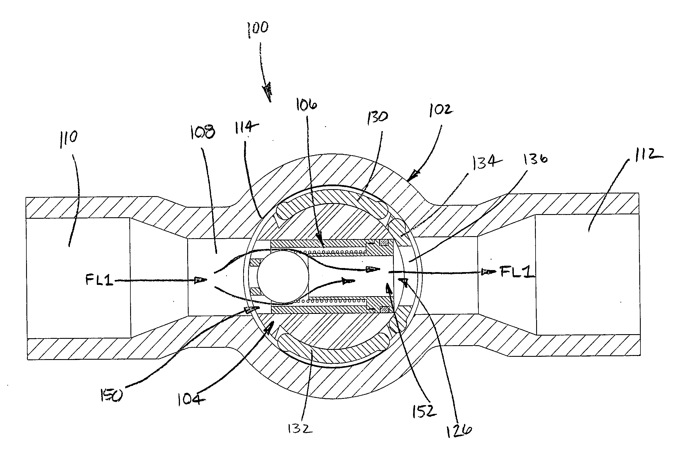
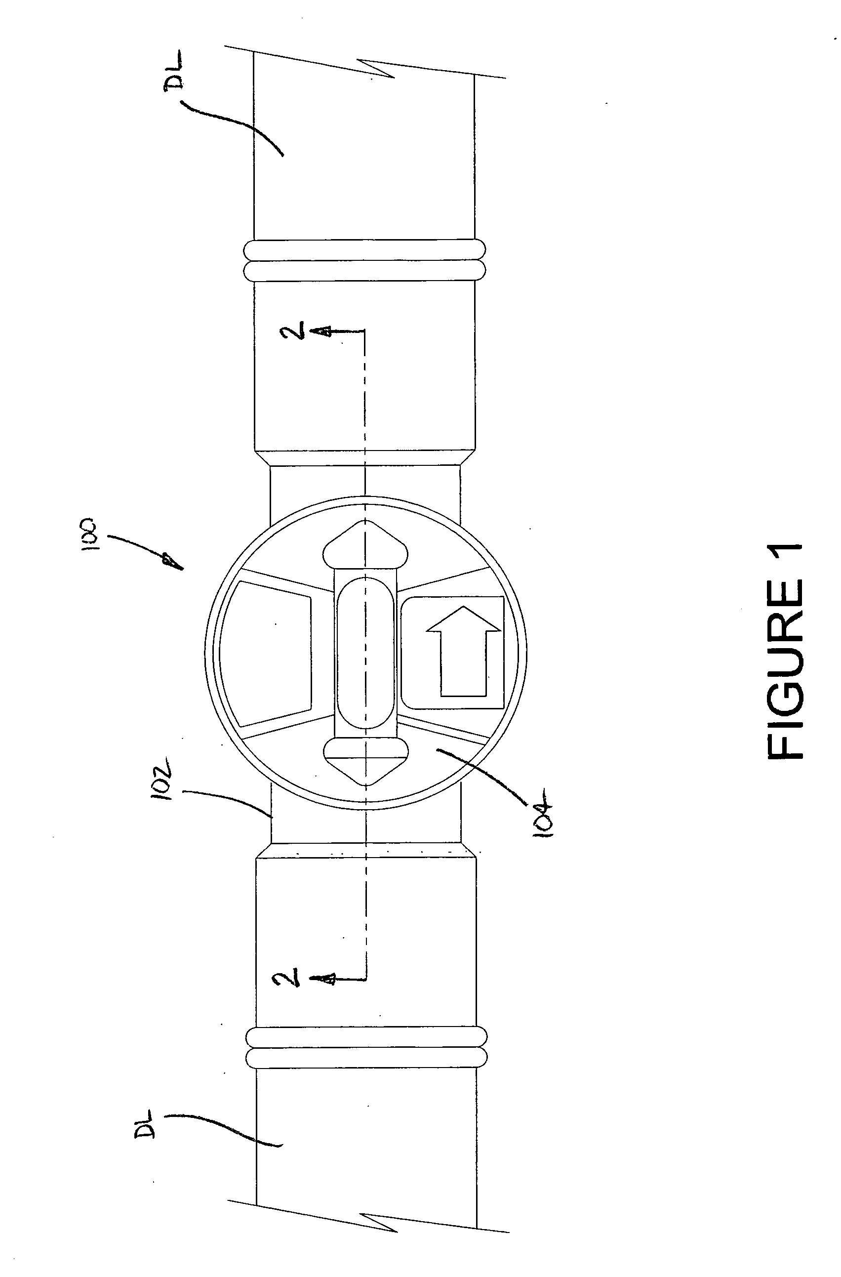
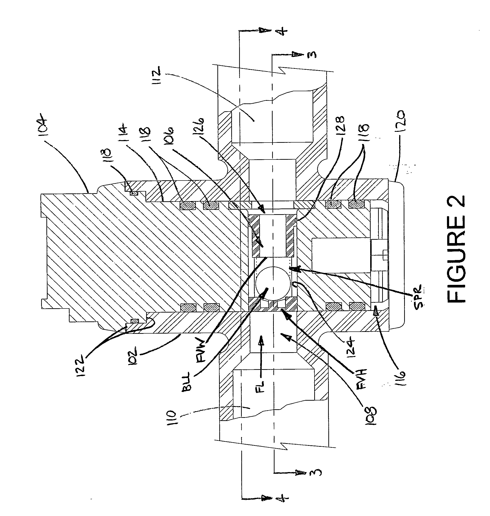
[0031] Turning now to the drawings wherein the showings are for the purposes of illustrating preferred embodiments of the invention only, and not for the purposes of limiting the invention, FIG. 1 shows a combination shut-off and excess flow valve 100 fluidically interconnected between two delivery lines DL, such as from a fluid distribution system (not shown), for example. Valve 100 includes a housing 102 and a valve body 104 supported on the housing. As shown in FIG. 2, valve 100 also includes an excess flow valve 106.

[0032] Housing 102 includes a passage 108 extending therethrough. The passage has an inlet portion 110 and an outlet portion 112 such that an associated fluid generally flows from the inlet portion toward the outlet portion as indicated by arrow FL. Housing 102 includes an inside wall 114 at least partially defining a generally cylindrical valve chamber 116 that receives valve body 104. A plurality of sealing members, such as o-rings 118, for example, are compressiv...


PUM


Abstract

A valve operable with an associated fluid delivery system having fluid flow therethrough includes a housing, a valve body and a resetable excess flow valve. The housing has a first passage and the valve body is disposed along the first passage and including a wall at least partially defining a second passage. The excess flow valve is supported along one of the first and second passages. The valve body is displaceable between a first position permitting flow through the second passage and a second position substantially shutting-off fluid flow and resetting the excess flow valve.

Description

[0001] This application claims the benefit from Provisional Patent Application No. 60 / 491,614 filed on Jul. 31, 2003, which is hereby incorporated herein by reference in its entirety.BACKGROUND [0002] The present invention broadly relates to the art of fluid delivery systems and, more particularly, to a combination shut-off and excess flow valve for use in association along transmission lines of such systems. [0003] The present invention relates generally to fluid delivery systems. It finds particular application in conjunction with underground gas distribution systems and will be described with particular reference thereto. However, it is to be appreciated that the invention is equally applicable for use in other environments, including above-ground installations, such as in industrial and / or commercial buildings, for example. Additionally, the present invention is particularly well suited for use with non-bypass type excess flow valves. However, it is to be distinctly understood t...

Claims


Application Information

Patent Timeline
IPC IPC(8): F16K5/04F16K17/30F16K27/06
CPCF16K5/0407F16K27/065F16K17/30Y10T137/0324Y10T137/7727Y10T137/7729Y10T137/7869Y10T137/8803
Inventor ROBISON, DAVID L.
Owner ELSTER PERFECTION CORP
Why Eureka
Try Eureka