
Method and apparatus for identifying a set of multiple items on conveyor system with multiread transponders

Inactive Publication Date: 2007-04-03
DATAMARS
View PDF12 Cites 16 Cited by
  • Summary
  • Abstract
  • Description
  • Claims
  • Application Information

AI Technical Summary

Benefits of technology

[0005]It is an object of the present invention to provide methods and apparatus for identifying multiple items on a conveyor using radio frequency multiread transponders in which the conveyor is arranged to either lift up or move down the items to be identified so that they are placed within a three dimensional antenna thereby enabling the items to be identified.
[0006]It is a further object of the invention to provide a three dimensional antenna which is free of any extraneous devices within the antenna and minimizes the emission of magnetic or electromagnetic radiation outside of the antenna and also minimizes a magnetic or electromagnetic noise from outside of the antenna affecting reading of the items within the carrier.
[0007]It is still a further object of the present invention to provide a radio frequency transponder having a rugged construction, which is of small size, and which is capable of withstanding severe environmental conditions and, particularly, severe thermocycling of the type which may occur by repeated use in an industrial laundry.

Problems solved by technology

A known common problem is the fact that if multiple items are placed randomly in a bag, a box or another carrier, it is necessary to read them in a three dimensional (3D) antenna.
In such cases it is necessary to build the antenna around the conveyor which gives several disadvantages like bigger antenna size, metal inside the antenna, motors inside the antenna.

Method used


Image

  • Method and apparatus for identifying a set of multiple items on conveyor system with multiread transponders
  • Method and apparatus for identifying a set of multiple items on conveyor system with multiread transponders
  • Method and apparatus for identifying a set of multiple items on conveyor system with multiread transponders

Examples


Embodiment Construction

)

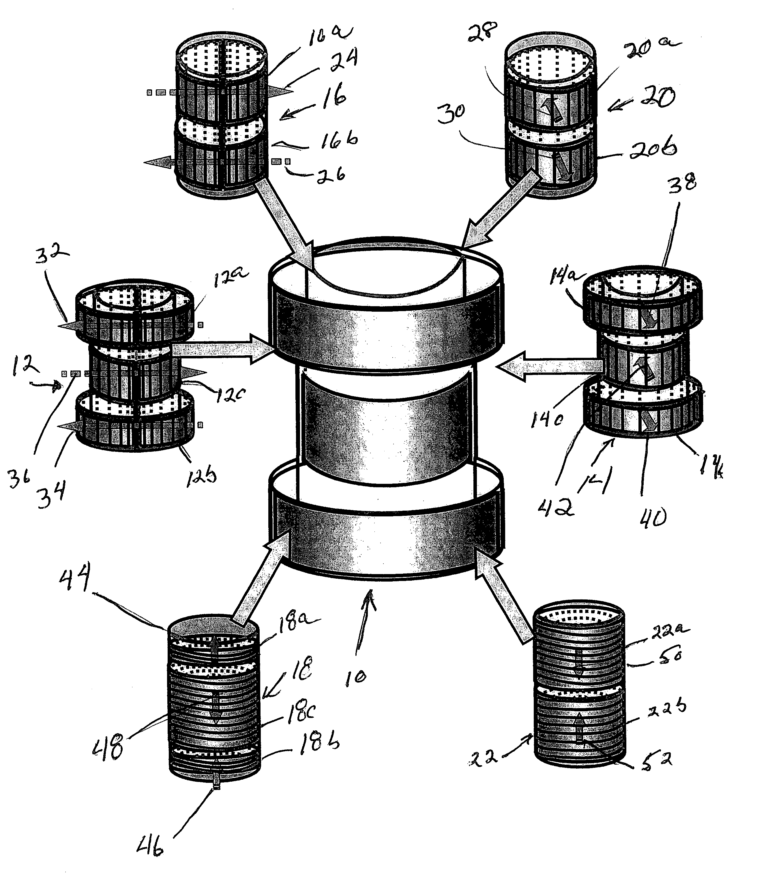
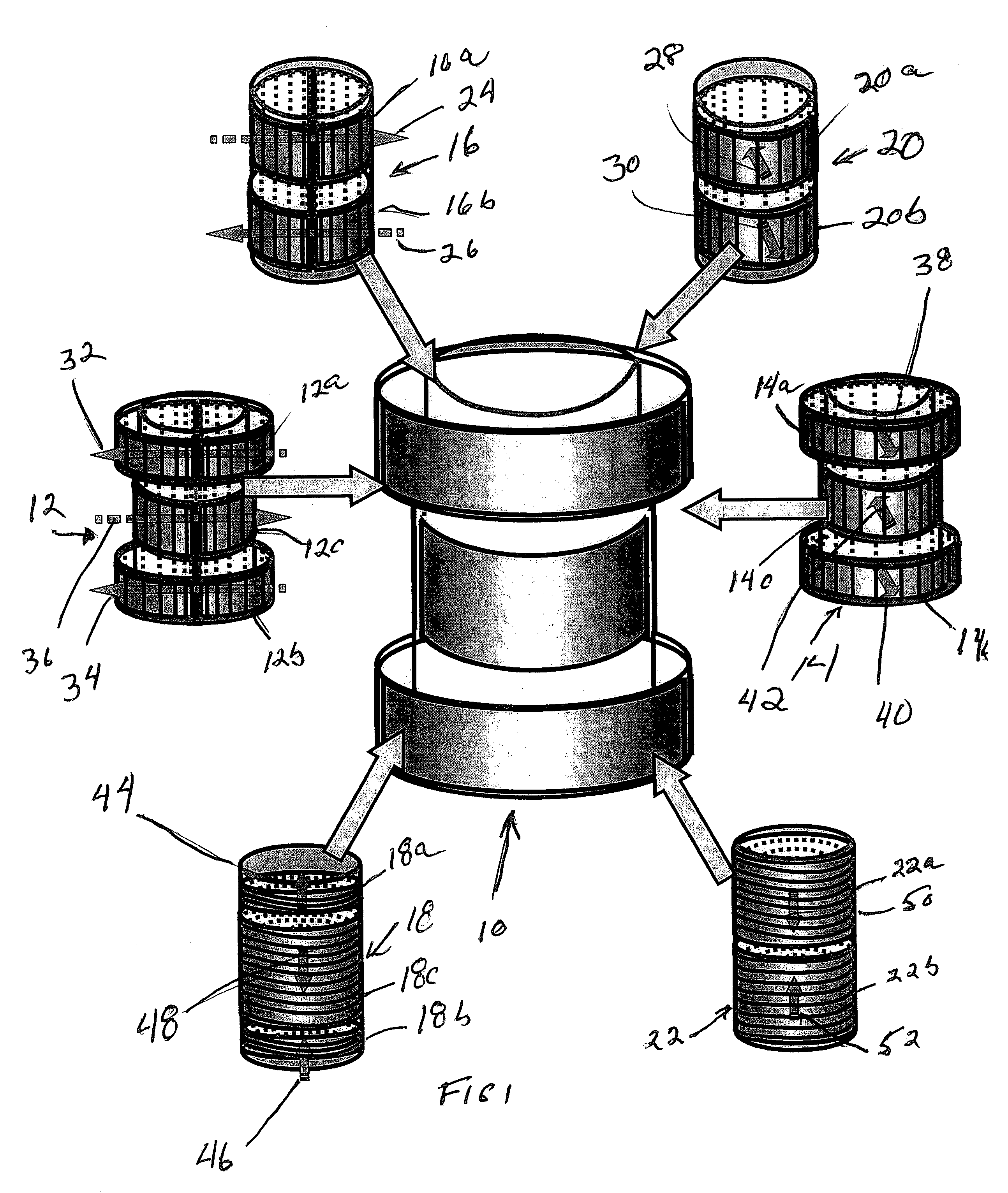
[0020]Referring now to the drawings and, in particular to FIG. 1, there is shown a three dimensional (3D) cylindrical antenna 10 embodying certain features of the invention. The 3D antenna 10 is composed of six individual antenna coils 12, 14, 16, 18, 20 and 22.

[0021]The antenna coils are arranged in a nested relationship such that the antenna coils 12 and 14 which are designated horizontal middle antenna coils are nested within each other. The other antenna coils 16, 18, 20 and 22 are then nested within the horizontal middle antenna coils 12 and 14.

[0022]The antenna coils 16 and 20 each have an upper portion (16a, 20a) and a lower portion (16b, 20b), the coils of which are wound about a horizontal axis to provide horizontal magnetic fields with different directions of flux as shown by the arrows 24, 26, 28 and 30. More specifically, the upper portion 16a of the antenna coil 16 provides a magnetic field which is directed horizontally from left to right (arrow 24) as shown in FIG. 1...


PUM


Abstract

A three dimensional (3D) radio frequency antenna is positioned on one side of a conveyor which has a movable part for moving items, each of which has a radio frequency transponder, into and out of the antenna such that the items when in the antenna are completely surrounded by the antenna. The 3D antenna includes a plurality of coils which provide a 3D reading field in which all transponders in the reading field may be interrogated and also includes noise compensation coils at opposite ends of the reading field to minimize electromagnetic radiation from the antenna and also minimize noise from external sources. The radio frequency transponder includes a housing, a substrate within the housing, an integrated circuit and a printed circuit board mounted on the substrate. A coil is mounted on the substrate such as to be spaced therefrom with the spacing of the coil from the substrate enabling the encapsulant to completely surround the coil.

Description

CROSS REFERENCE TO RELATED APPLICATIONS[0001]This application is based on and claims priority to U.S. Provisional Application Ser. Nos. 60 / 391,402, filed Jun. 24, 2002 by Parvis Hassan-Zade and Roberto Dotti entitled “MULTIREAD TRANSPONDER” and 60 / 391,265, filed Jun. 24, 2002 by Parvis Hassan-Zade and Roberto Dotti entitled “A METHOD AND APPARATUS FOR IDENTIFYING A SET OF MULTIPLE ITEMS ON A CONVEYOR SYSTEM WITH MULTIREAD TRANSPONDERS”, the entire disclosure of each of the provisional applications is incorporated by reference herein.BACKGROUND OF THE INVENTION[0002]This invention is related to identifying multiple items with multiread transponders and, more particularly, to methods and apparatus for identifying a set of multiple items on a conveyor system using radio frequency multiread transponders.[0003]Known radio frequency identification technology has the ability to identify multiple items simultaneously thanks to a multiread ability. A known common problem is the fact that if ...

Claims


Application Information

Patent Timeline
IPC IPC(8): G06F19/00G06K7/00G06K7/08G06K7/10G06K19/04G06K19/077
CPCG06K7/0008G06K7/10336G06K7/10346G06K19/041G06K19/07749G06K19/07758
Inventor HASSAN-ZADE, PARVISDOTTI, ROBERTOISHII, TAKAMASAJOBIN, JEAN-MARC
Owner DATAMARS
Learn More