
High density optical packaging

a high-density, optical packaging technology, applied in the direction of optical elements, electromagnetic repeaters, instruments, etc., can solve the problem of the relative narrow bandwidth within which this form of resonant amplification occurs

Inactive Publication Date: 2007-03-27
OPTIC153 LLC
View PDF11 Cites 18 Cited by
  • Summary
  • Abstract
  • Description
  • Claims
  • Application Information

AI Technical Summary

Benefits of technology

"The present invention solves problems associated with conventional optical communication systems by providing a repeater for use in undersea optical communication. The repeater includes a pressure vessel, a frame, and optical signal amplification circuitry. The optical signal amplification circuitry includes at least 500 passive optical components and is interconnected by at least 1000 meters of optical fiber. Additionally, the invention provides an optical component tray with cavities for holding fiber optic components, an area for winding optical fiber, and at least one guide groove. These improvements facilitate the efficient and reliable communication of optical signals in underwater environments."

Problems solved by technology

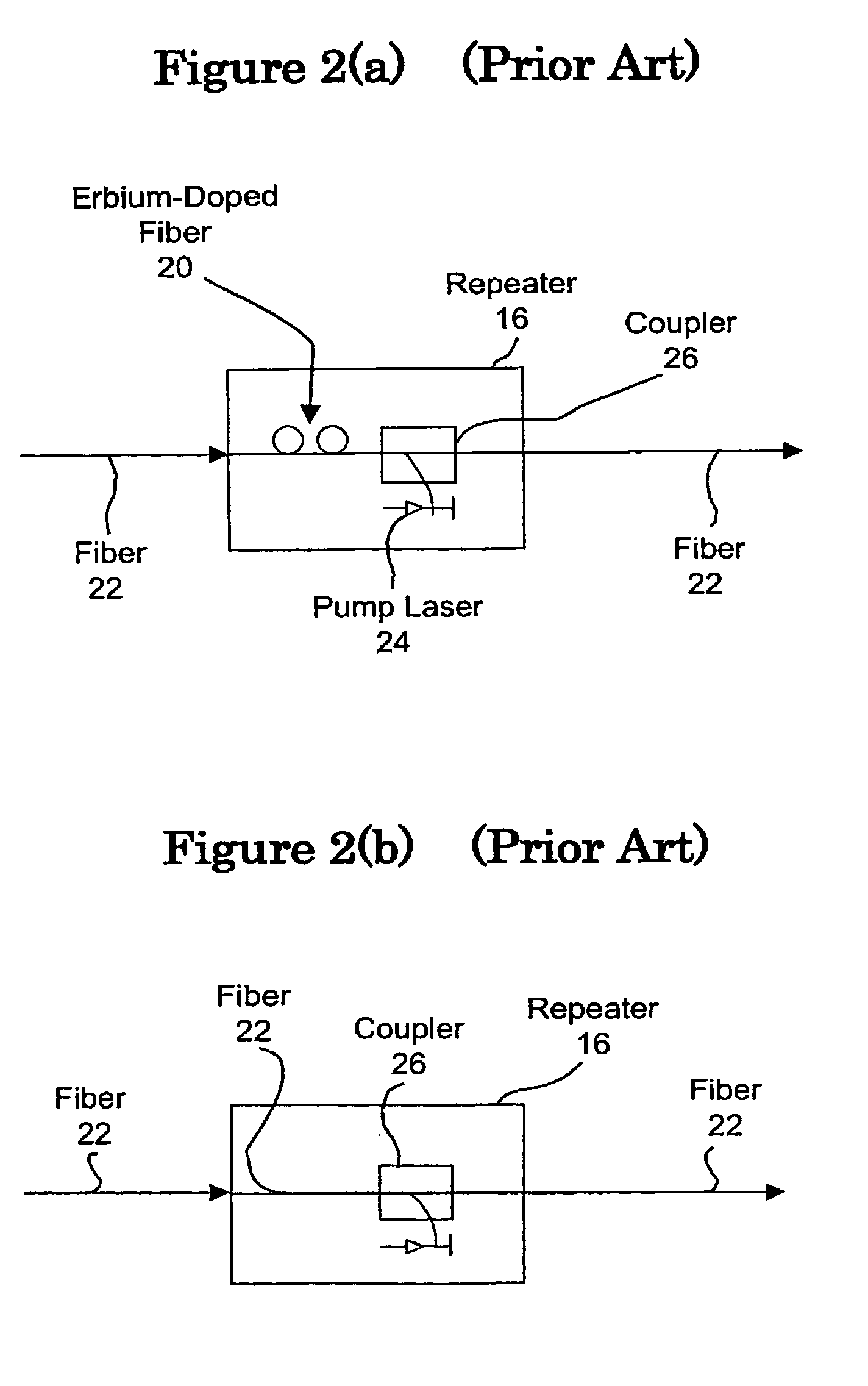
One drawback of EDFA amplification techniques is the relatively narrow bandwidth within which this form of resonant amplification occurs, i.e., the so-called erbium spectrum.
However, as the limits of EDFA amplification are now being reached, recent efforts have begun to explore the design issues associated with supplementing, or replacing, EDFA amplification technology with Raman amplification technology.

Method used


Image

  • High density optical packaging
  • High density optical packaging
  • High density optical packaging

Examples


Embodiment Construction

[0039]In the following description, for the purposes of explanation and not limitation, specific details are set forth, such as particular systems, networks, software, components, techniques, etc., in order to provide a thorough understanding of the present invention. However, it will be apparent to one skilled in the art that the present invention may be practiced in other embodiments that depart from these specific details. In other instances, detailed descriptions of known methods, devices and circuits are abbreviated or omitted so as not to obscure the present invention.

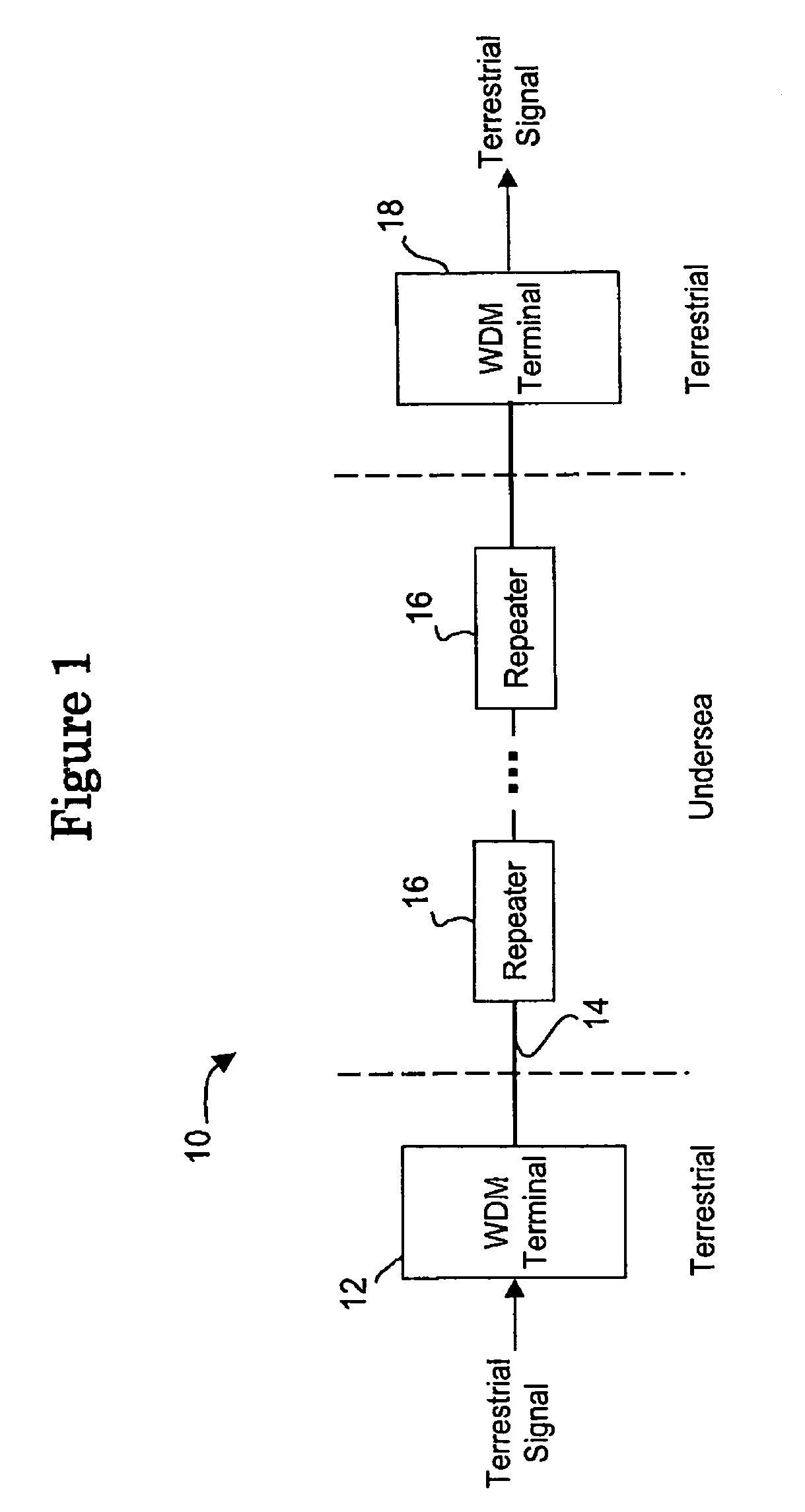
[0040]Repeaters which enable high power optical signal transmission systems can be employed in systems such as those depicted in FIG. 1, i.e., submarine optical communication systems, or in terrestrial systems. For the purpose of illustration, rather than limitation, an exemplary Raman-amplified system is described below for context. Those skilled in the art will appreciate that many different system configuratio...


PUM


Abstract

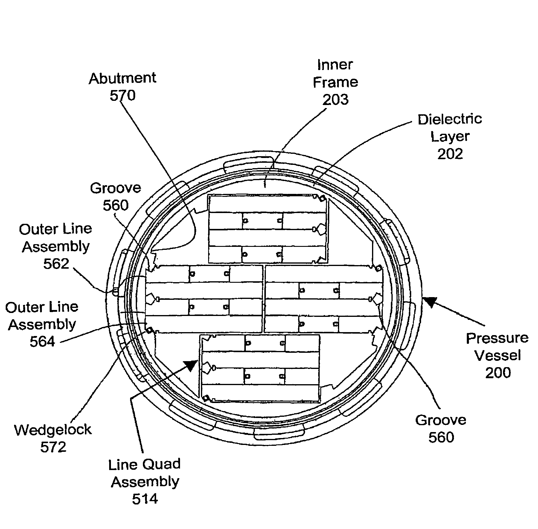
Repeaters for use in amplifying optical data signals transmitted through undersea fiber optic cables are disclosed. Raman amplification schemes using 100 or more pump lasers are integrated into industry standard sized pressure vessels for amplifying optical data signals transmitted through one or more fiber optic pairs. Such repeaters include high density packaging to permit numerous active and passive optical components, as well as significant lengths of optical fiber, to reside within legacy sized pressure vessels.

Description

RELATED APPLICATION[0001]This application is related to, and claims priority from, U.S. Provisional Patent Application Ser. No. 60 / 326,455, entitled “High Density Optical Packaging”, filed on Oct. 3, 2001, the disclosure of which is incorporated here by reference.BACKGROUND[0002]From the advent of the telephone, people and businesses have craved communication technology and its ability to transport information in various formats, e.g., voice, image, etc., over long distances. Typical of innovations in communication technology, recent developments have provided enhanced communications capabilities in terms of the speed at which data can be transferred, as well as the overall amount of data being transferred. As these capabilities improve, new content delivery vehicles, e.g., the Internet, wireless telephony, etc., drive the provision of new services, e.g., purchasing items remotely over the Internet, receiving stock quotes using wireless short messaging service (SMS) capabilities etc...

Claims


Application Information

Patent Timeline
Patent Type & Authority Patents(United States)
IPC IPC(8): H01S3/00G02B6/44H04B10/16H04B10/17H04B10/29
CPCH04B10/2918H04B10/2916G02B6/4442G02B6/4428H04B10/298
Inventor ADAMS, SR., ROBERT M.SEAL, LOWELLPOHL, BRENT R.GOLDSTEIN, BRETT
Owner OPTIC153 LLC
Learn More