Gas chromatograph and expired air component analyzer
a technology of gas chromatograph and analyzer, which is applied in the direction of instruments, specific gravity measurement, and mechanical means, can solve the problems of inability to achieve qualitative/quantitative analysis with reliability, and the device is easily large as a whole, so as to achieve reliable analysis and stabilize the baseline output of the detector
- Summary
- Abstract
- Description
- Claims
- Application Information
AI Technical Summary
Benefits of technology
Problems solved by technology
Method used
Image
Examples
first embodiment
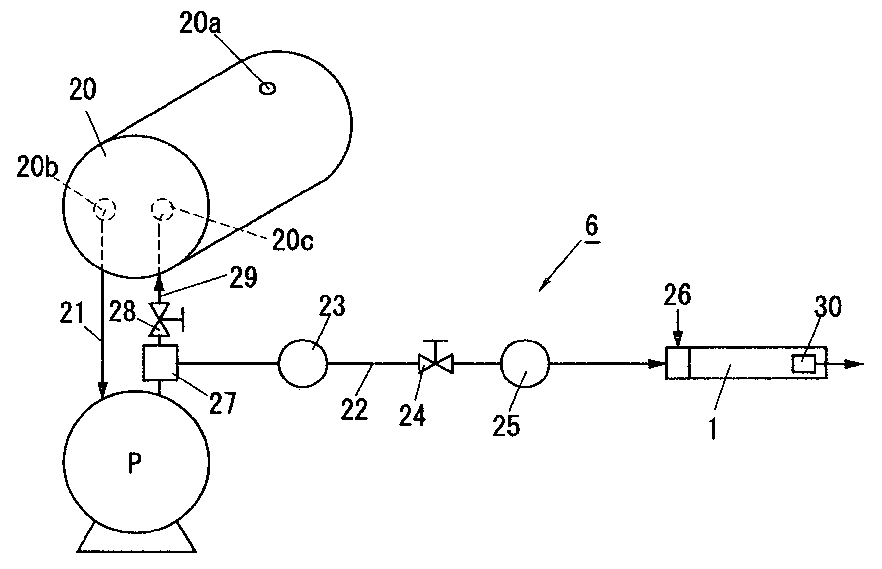
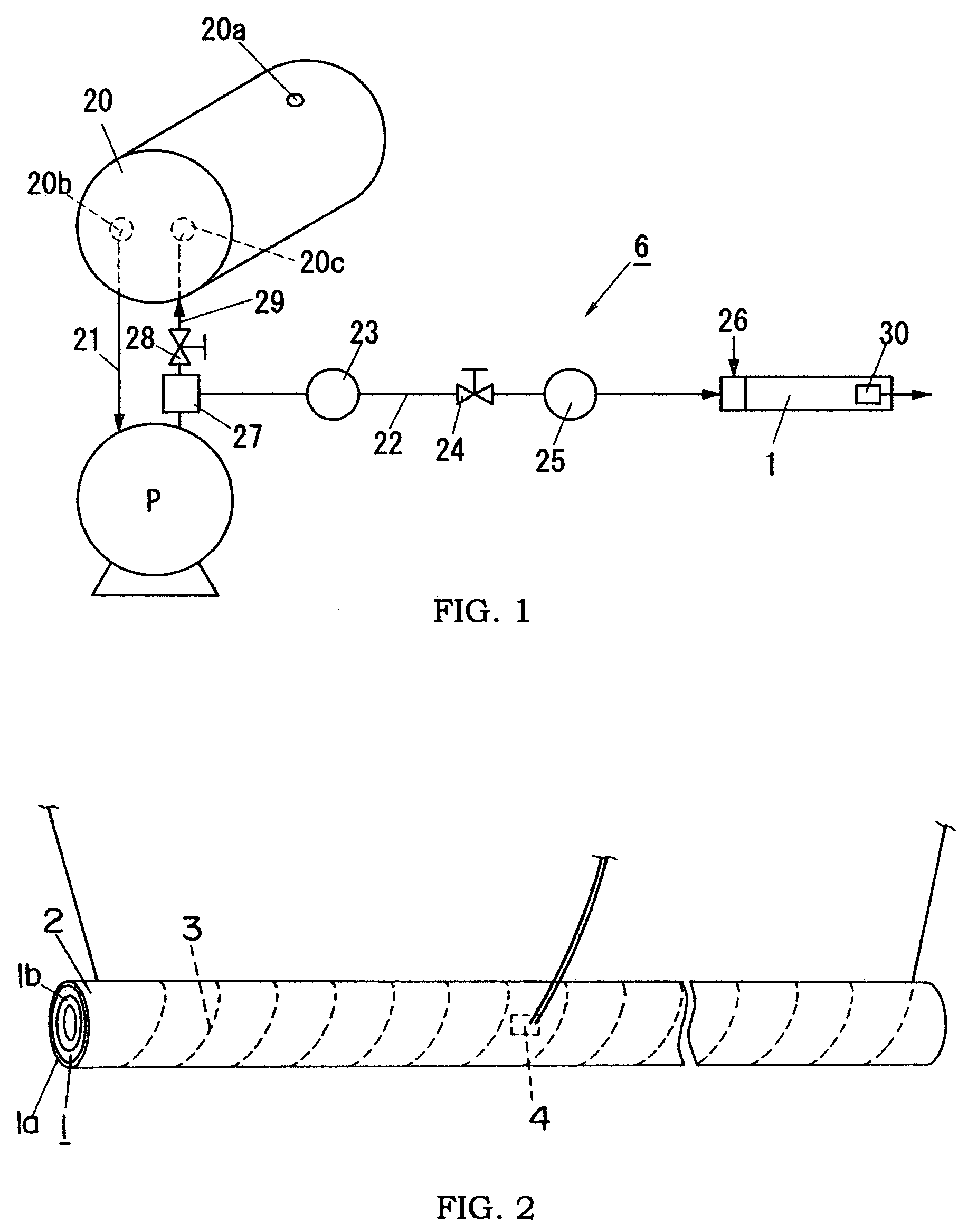
[0037]FIG. 1 is a schematic diagram illustrating a flow channel configuration of a gas chromatograph 6 of the present embodiment. This gas chromatograph 6 is mainly composed of a gas separation column 1 accommodating a member of causing a flow delay depending on gas component, air pump P for pressure feeding an air as a carrier gas to the gas separation column 1, gas supply port (hereinafter referred to as a gas injection port) 26 formed in a gas flow channel 22 extending between the air pump P and the gas separation column 1 to supply a subject gas including a target gas component to be detected into the carrier gas flowing in the gas flow channel 22, buffer tank 20 disposed upstream of the air pump, and a detector 30 for detecting the gas component of the subject gas supplied into the gas separation column 1.
[0038]The buffer tank 20 is formed in a bottle shape having a suction port 20a of a small aperture communicated with outside, discharge port 20b, and a return port 20c. The ai...
second embodiment
[0067]As described above, the first embodiment is characterized in that the buffer tank 20 is disposed upstream of the air pump P, and a part of the air (excessive air) supplied from the pump is returned to the buffer tank 20. However, in the present embodiment, as shown in FIG. 11, a buffer tank 20 is formed in a gas flow channel between a flow regulator 24 and a gas injection port 26. That is, the air sucked by an air pump P is flow controlled by the flow regulator 24, and then sent as the carrier gas to a gas separation column 1 through the buffer tank 20. When the air pump P has a large suction capacity, the excessive air may be discharged outside. Other configurations are substantially the same as the first embodiment. Therefore, duplicate explanations are omitted.
third embodiment
[0068]The retention time described above depends on the flow amount of the carrier gas. Therefore, as the flow amount of the carrier gas increases, the retention time becomes earlier (shorter). In addition, there is a case that it takes a very long time (slow) to come out from the gas separation column 1 with respect to a specific gas component. In such a case, there is a fear that the detection time is extended, and the conversion of concentration becomes inaccurate because the detector output is provided by a broad peak.
[0069]Therefore, the gas chromatograph of the present embodiment is characterized by shortening the detection time of the gas component having a long retention time, and performing a control such that the flow amount of the carrier gas is increased according to a required pattern from the time of detecting gas injection to make the peak of the detector output sharp.
[0070]FIG. 12 is a schematic diagram showing a flow channel configuration of this gas chromatograph. ...
PUM
| Property | Measurement | Unit |
|---|---|---|
| volume | aaaaa | aaaaa |
| retention time | aaaaa | aaaaa |
| gas chromatograph | aaaaa | aaaaa |
Abstract
Description
Claims
Application Information
 - R&D
- Intellectual Property
- Life Sciences
- Materials
- Tech Scout
- Unparalleled Data Quality
- Higher Quality Content
- 60% Fewer Hallucinations
Browse by: Latest US Patents, China's latest patents, Technical Efficacy Thesaurus, Application Domain, Technology Topic, Popular Technical Reports.
© 2025 PatSnap. All rights reserved.Legal|Privacy policy|Modern Slavery Act Transparency Statement|Sitemap|About US| Contact US: help@patsnap.com


