
Superconducting fault current limiter

a fault current limiter and superconductor technology, applied in the direction of superconducting magnets/coils, superconductor devices, magnetic bodies, etc., can solve the problem of adding significantly to the overall device cos

Inactive Publication Date: 2007-03-20
ZENERGY POWER
View PDF9 Cites 45 Cited by
  • Summary
  • Abstract
  • Description
  • Claims
  • Application Information

AI Technical Summary

Problems solved by technology

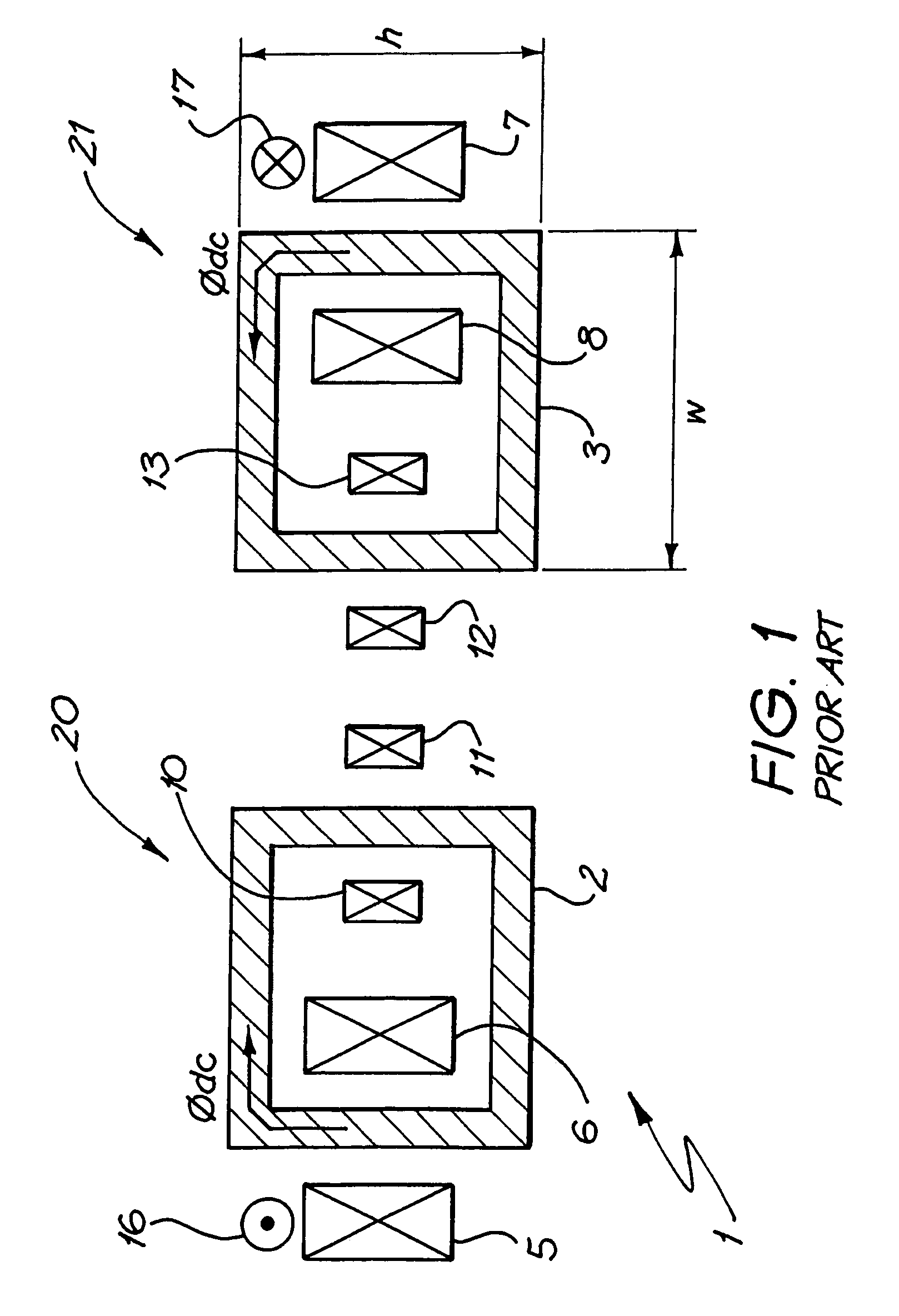
Such a large number of HTS DC windings adds significantly to the expense of the overall device.

Method used


Image

  • Superconducting fault current limiter
  • Superconducting fault current limiter
  • Superconducting fault current limiter

Examples


Embodiment Construction

[0027]In the preferred embodiment, there are disclosed methods for the construction of a compact HTS FCL. Both single phase and three phase arrangements are disclosed.

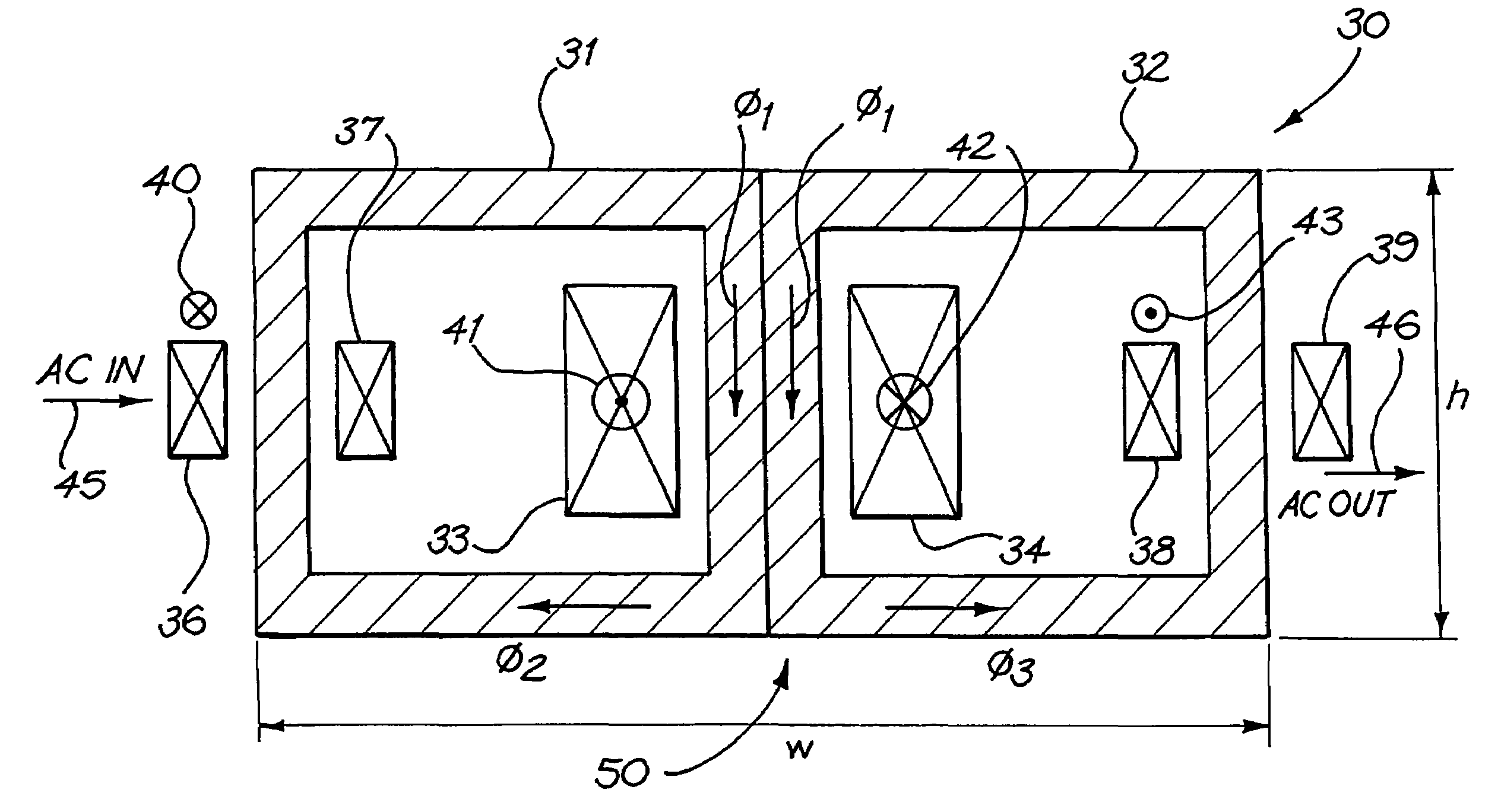
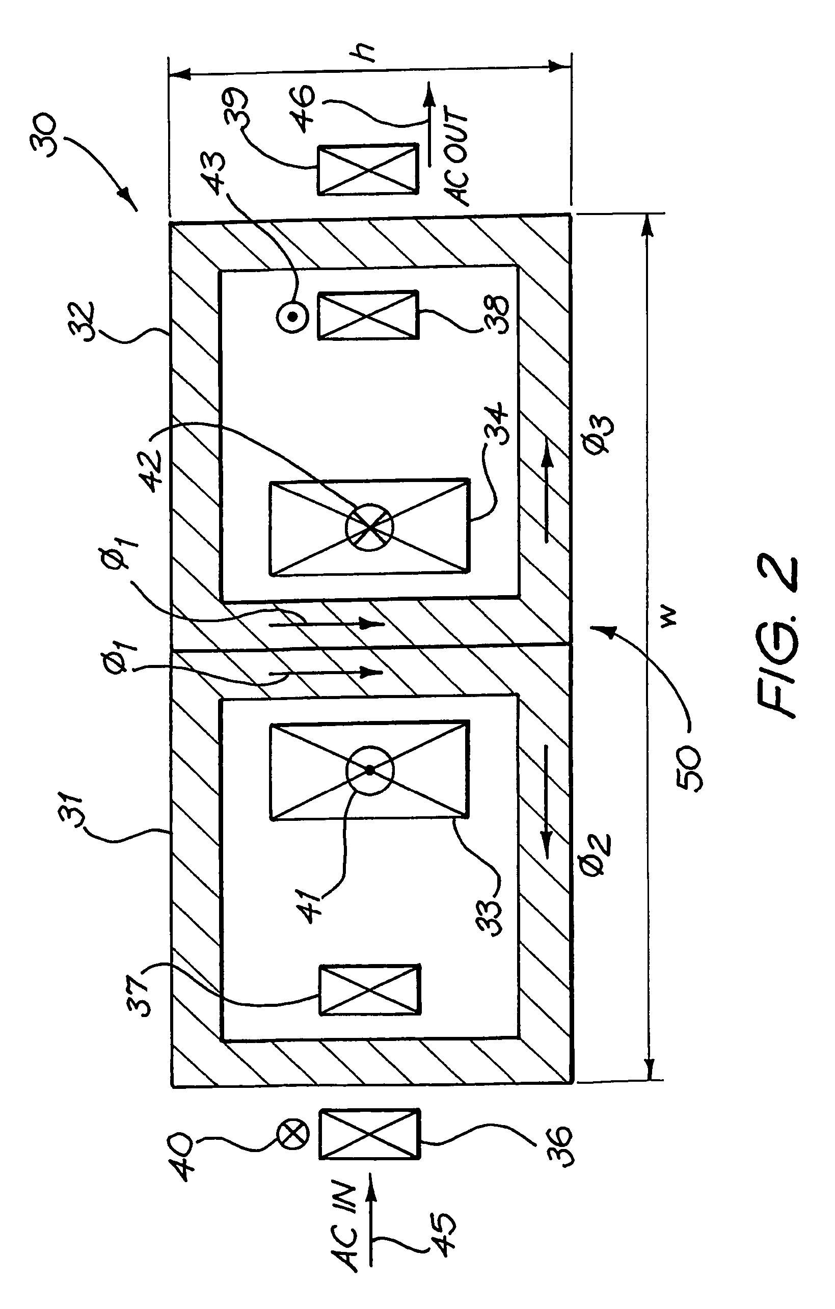
[0028]Turning initially to FIG. 2, there is illustrated schematically a sectional view of an initial design arrangement 30 for a split core single phase HTS FCL. The unit 30 includes a split core having components 31, 32 so as to allow for a substantial reduction in foot print size. In the arrangement 30, the DC saturated core windings are internally located 33. The AC linkage windings are also provided in pairs 36 and 38. The current carrying directions are as indicated via standard dot notation 40, 41, 42, and 43. The AC in port is assumed to occur at port 45 and the AC out port at port 46.

[0029]The design of the arrangement 30 and, in particular, the dimensions of the core 50 are in accordance with certain rules. The design is a compromise between the DC current and the level of saturation required. In an example ca...


PUM

PropertyMeasurementUnit
frequencyaaaaaaaaaa
critical temperatureaaaaaaaaaa
magnetic permeabilityaaaaaaaaaa

Abstract

A superconducting current limiting device (30) comprising: an interconnected high magnetic permeability structure including a central core (50) interconnected to at least a first and second arm (31, 32) branching off therefrom; a superconductive coil (33, 34) surrounding the central core for biasing the central core; a first alternating current coil (36, 37) surrounding the first arm and interconnected to an alternating current source; a second alternating current coil (38, 39) surrounding a second arm and interconnected to an alternating current load; the first and second alternating current coils being magnetically coupled to the central core wherein the device operates so as to limit the current passing through the device upon the occurrence of a fault condition in the load.

Description

FIELD OF THE INVENTION[0001]The present invention relates to the field of superconductor fault current limiters and, in particular, discloses a High Temperature Superconductor (HTS) Fault Current Limiter (FCL) having a compact design utilising either split or solid limb cores or a combination of both.BACKGROUND OF THE INVENTION[0002]The discovery of high temperature superconductors has lead to the development of a number of applications for their use. Superconductors are known to have the property that they have zero direct current (DC) resistance below a critical temperature Tc. They also have zero DC resistance below a critical current Ic and a critical magnetic field Bc.[0003]One potential use of HTS is in FCLs. HTS can be used in FCLs in a number of ways, and the use of HTS to limit fault currents is an elegant solution to the ever-present short circuit threat in power networks.[0004]There are several different methods to incorporate HTS in an FCL design. FIG. 1 illustrates sche...

Claims


Application Information

Patent Timeline
Patent Type & Authority Patents(United States)
IPC IPC(8): H02H9/00H01F36/00H01F6/00H01L39/16H02H9/02
CPCH01F6/00H01F36/00Y02E40/66Y10S505/85H01F2006/001Y02E40/60
Inventor DARMANN, FRANCIS ANTHONYBEALES, TIMOTHY PAUL
Owner ZENERGY POWER
Learn More