
Method for correcting unadjusted threshold arrays for halftoning by use of parameterized transfer functions that generate adjusted threshold arrays at run time

Inactive Publication Date: 2007-03-13
LEXMARK INT INC
View PDF8 Cites 9 Cited by
  • Summary
  • Abstract
  • Description
  • Claims
  • Application Information

AI Technical Summary

Benefits of technology

[0015]Accordingly, it is a primary advantage of the present invention to provide an image forming apparatus such as a printer that stores a minimum number of threshold arrays in non-volatile memory, and at run time creates adjusted threshold arrays to meet the precise print job requirements, such as for the appropriate colors and appropriate types of print media.
[0016]It is another advantage of the present invention to provide an image forming apparatus such as a printer that stores a minimal number of unadjusted threshold arrays consisting of numeric elements that have a greater precision than the numeric elements of adjusted threshold arrays that are derived at run time and which benefit from the greater precision of the unadjusted arrays to more nearly match the printer's response to the human visual perceptual levels.
[0017]It is a further advantage of the present invention to provide an image forming apparatus such as a printer that stores a minimal number of unadjusted threshold arrays consisting of numeric elements that have a greater precision than the numeric elements of adjusted threshold arrays that are derived at run time and which benefit from the greater precision of the unadjusted arrays to create a predetermined non-linear response that closely matches a response of another printing device, as desired for a specific printing application.
[0018]It is a yet further advantage of the present invention to provide an image forming apparatus such as a printer that stores a minimal number of unadjusted threshold arrays and generates adjusted threshold arrays that are derived at run time and which compensate for the gradual change in darkness of the printer response due to the aging of an electrophotographic (EP) process cartridge over its useful life, by providing new transfer functions that further correct the adjusted threshold arrays after predetermined amounts of usage of the EP process cartridge.
[0019]It is yet another advantage of the present invention to provide an image forming apparatus such as a printer that stores a minimum number of unadjusted threshold arrays along with a set, of transfer function equations that can quickly produce a set of adjusted threshold arrays that are minimal in number to reduce memory requirements, and further that are produced for the specific print job requirements, such as the appropriate colors to be printed as well as the type of print media to be printed upon.
[0020]It is still a further advantage of the present invention to provide an image forming apparatus such as a printer that stores a minimal number of unadjusted threshold arrays in a packed memory configuration to minimize the amount of memory space required in a non-volatile memory circuit, and to provide an unpacking routine that quickly re-configures the unadjusted threshold array data in a format that allows quick access and application of a set of transfer function equations to derive a set of adjusted threshold arrays to be stored in the printer's RAM circuit.

Problems solved by technology

(Some printers may provide a single threshold array to be used for all colors, but the visual results are not pleasing.)
Early printers may have used unadjusted threshold arrays to produce their final printed outputs, however, such printers usually lose tone levels, and at best exhibit crude approximations to the desired perceptual tone levels.
This method saves memory space, but can be restrictive concerning the number of dots that must be placed on the page for different tone levels.
Since being restricted to adding a fixed number of dots at each level reduces the number of distinct intensity levels, accuracy will suffer.
Unfortunately, this also increases the size of both the one-dimensional arrays and the unadjusted screens, which are both stored in the printer when using the array mapping method.
Nevertheless, the memory storage space is quite large for any threshold arrays of meaningful precision.
However, a separate array must be generated for each combination of color and type of paper, and therefore, a large amount of memory is required to store each of the separate, adjusted threshold arrays.
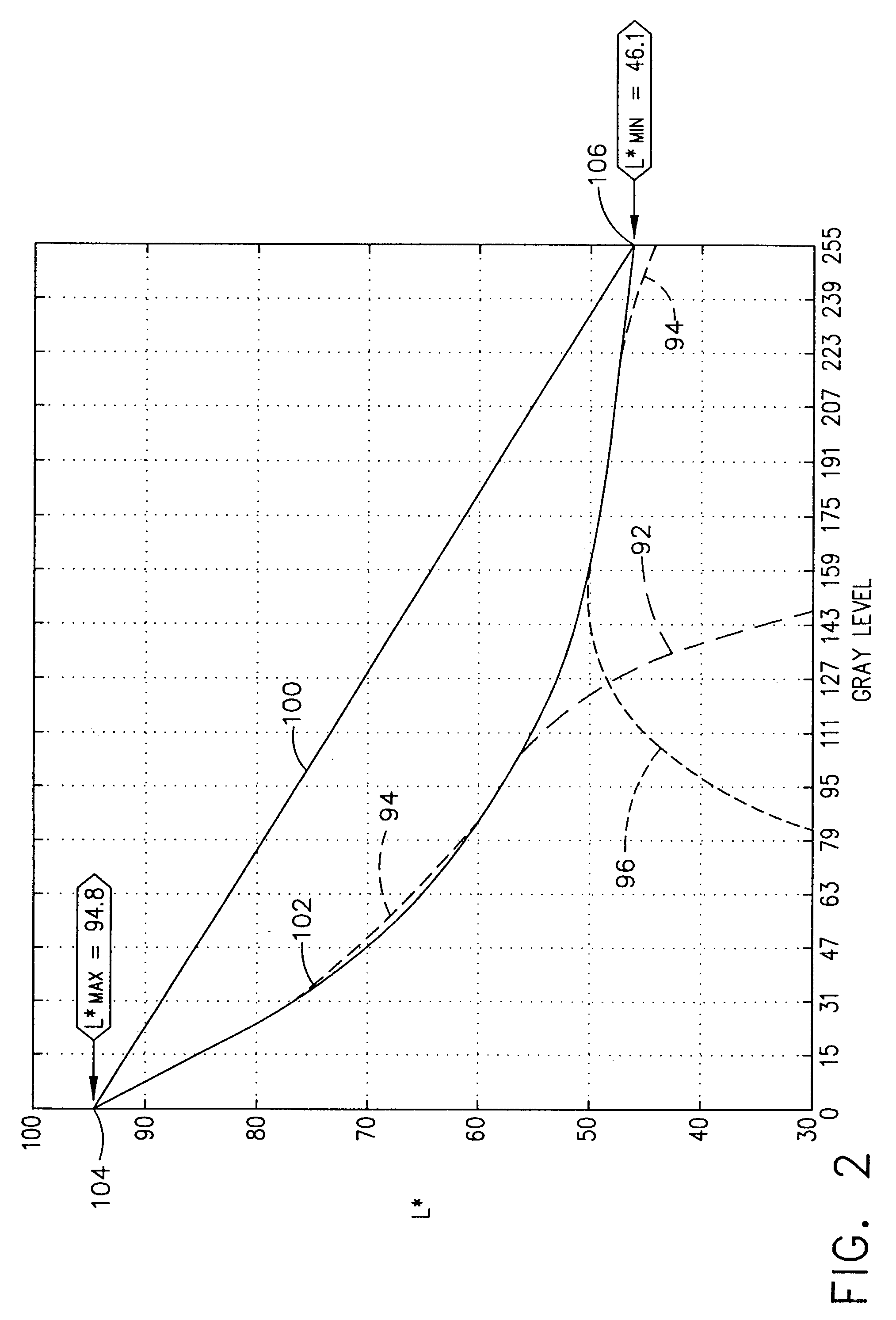
While the prior art methodology works well for many conventional printers, a large amount of memory storage space is required to store the corrected threshold array that is generated or derived by applying the mirror image transfer function curve to correct for the printer's non-linear actual response curve.
Moreover, since correcting for each printer color and print media type will lead to a large number of possible combinations, it has been common in the prior art for the conventional printers to store a large number of such adjusted threshold arrays in their non-volatile memory, such as in the printer's ROM, thereby requiring substantial amounts of memory space.

Method used


Image

  • Method for correcting unadjusted threshold arrays for halftoning by use of parameterized transfer functions that generate adjusted threshold arrays at run time
  • Method for correcting unadjusted threshold arrays for halftoning by use of parameterized transfer functions that generate adjusted threshold arrays at run time
  • Method for correcting unadjusted threshold arrays for halftoning by use of parameterized transfer functions that generate adjusted threshold arrays at run time

Examples


Embodiment Construction

[0047]Reference will now be made in detail to the present preferred embodiment of the invention, an example of which is illustrated in the accompanying drawings, wherein like numerals indicate the same elements throughout the views.

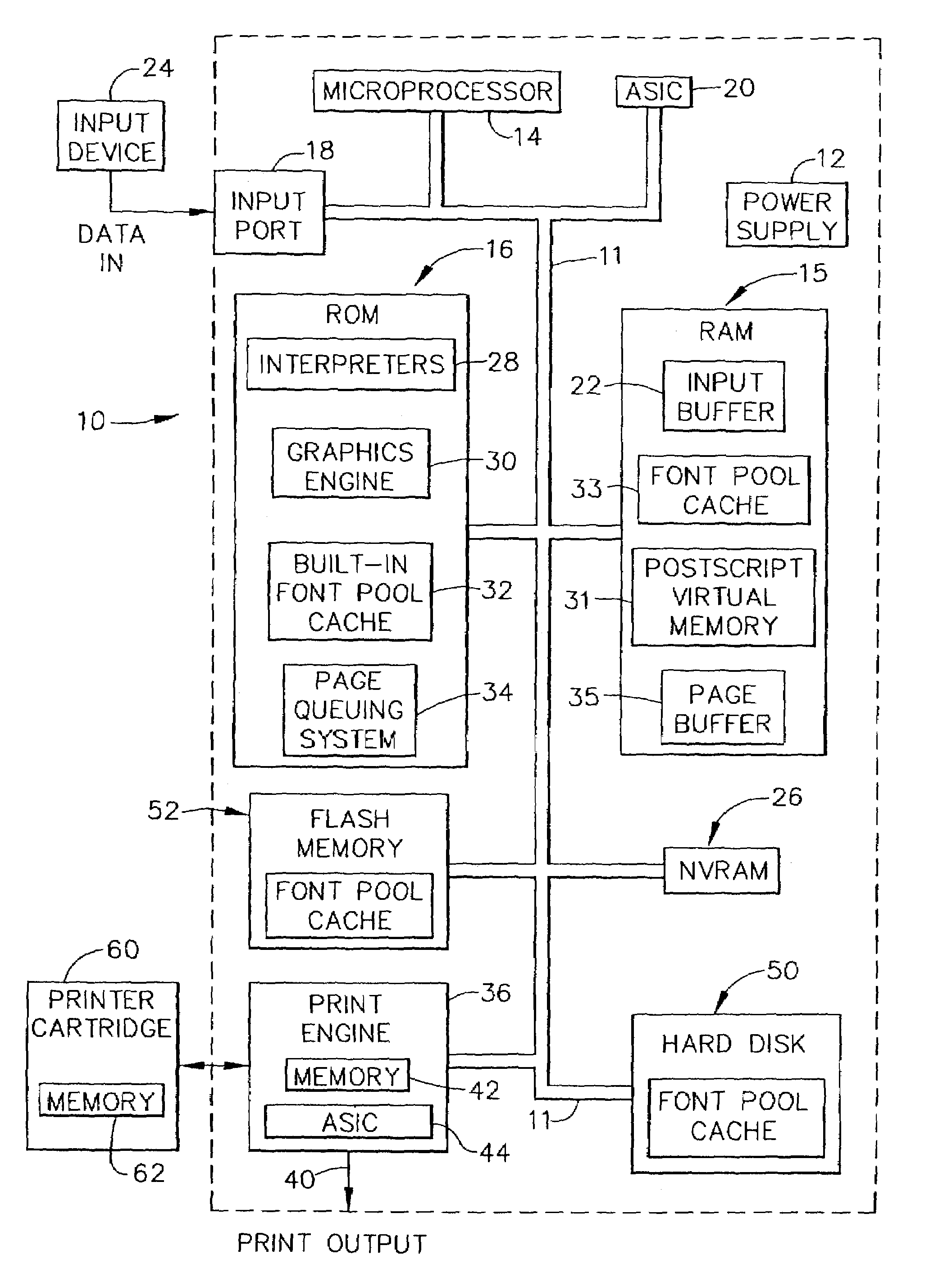
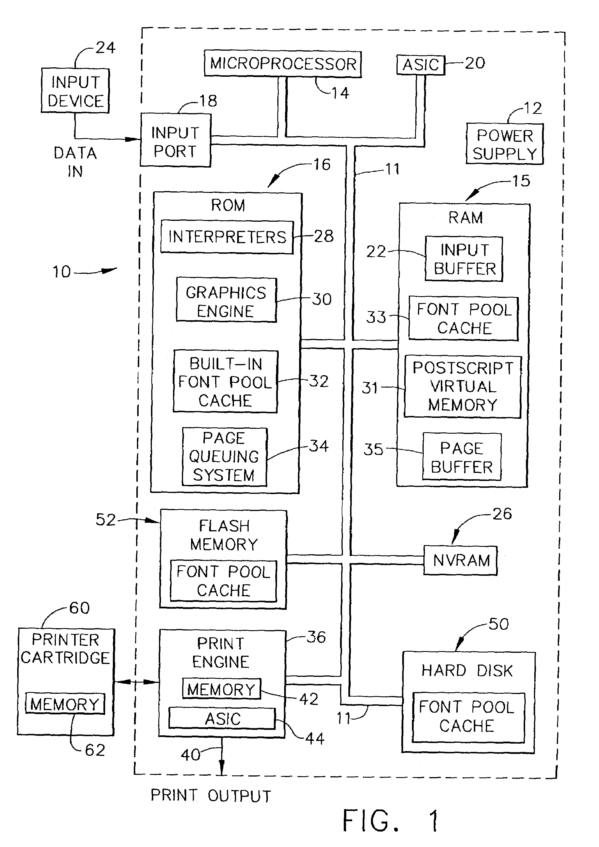
[0048]Referring now to the drawings, FIG. 1 shows a hardware block diagram of a laser printer generally designated by the reference numeral 10, although virtually the same components will be found on many ink jet printers. Laser printer 10 will preferably contain certain relatively standard components, such as a DC power supply 12 which may have multiple outputs of different voltage levels, a microprocessor 14 having address lines, data lines, and control and / or interrupt lines, Read Only Memory (ROM) 16, and Random Access Memory (RAM) 15, which is divided by software operations into several portions for performing several different functions.

[0049]Laser printer 10 also contains at least one input port, or in many cases several types of input ports, as de...


PUM


Abstract

A printer that stores a minimal number of unadjusted stochastic threshold arrays in non-volatile memory, in which the unadjusted threshold arrays are used to generate adjusted threshold arrays at run time by use of special parameterized transfer functions. The unadjusted array for a particular color is stored in the printer's ROM and preferably is stored in a packed configuration to save memory space. The parameterized transfer functions are used to convert the unadjusted threshold data into adjusted threshold data for each color and type of print media. These parameterized transfer functions are stored in the printer's non-volatile memory, and take up very little memory space. In a preferred embodiment, the unadjusted threshold array comprises a 128 row by 128 column sized array, and each element of this array comprises a 10-bit number. When a parameterized transfer function is applied to this unadjusted array, the resulting numeric values for the adjusted array elements are produced as 8-bit numeric values. The greater precision in the originating unadjusted array provides more perceptual levels of intensity (i.e., color brightness), which is particularly important at the lighter shades of each color. The adjusted threshold arrays add only the number of dots per gray level (i.e., per differential threshold array level) that are required to provide a printer response that very nearly approximates the human eye perceptual differential response of intensity.

Description

CROSS-REFERENCE TO RELATED APPLICATIONS[0001]The present application is a divisional to application Ser. No. 09 / 442,211, titled “METHOD AND APPARATUS FOR CORRECTING UNADJUSTED THRESHOLD ARRAYS FOR HALFTONING BY USE OF PARAMETERIZED TRANSFER FUNCTIONS THAT GENERATE ADJUSTED THRESHOLD ARRAYS AT RUN TIME,” filed on Nov. 17, 1999 now U.S. Pat No. 6,512,597.TECHNICAL FIELD[0002]The present invention relates generally to image forming equipment and is particularly directed to printers of the type which halftone color or black and white images. The invention is specifically disclosed as a printer that provides a 10-bit unadjusted stochastic threshold array, and applies one or more parameterized transfer function equations at run time to the unadjusted array to derive an 8-bit adjusted threshold array, thereby improving perceptual printer response while saving memory space.BACKGROUND OF THE INVENTION[0003]Threshold arrays have been used for years to accomplish halftoning for image forming e...

Claims


Application Information

Patent Timeline
IPC IPC(8): H04N1/405
CPCH04N1/4051
Inventor COOPER, BRIAN EDWARDDAMON, BRIAN WESLEYROBINSON, PAUL ATHANASIUSWADE, THOMAS CAMPBELL
Owner LEXMARK INT INC
Learn More