
Method and apparatus for determining a bidirectional reflectance distribution function, subsurface scattering or a bidirectional texture function of a subject

a bidirectional reflectance and function technology, applied in the field of determining the bidirectional reflectance distribution function of a subject, can solve the problems of difficult to obtain a dense sampling, incongruous real world surfaces, and low accuracy of the results,

Inactive Publication Date: 2007-03-13
NEW YORK UNIV
View PDF3 Cites 70 Cited by
  • Summary
  • Abstract
  • Description
  • Claims
  • Application Information

AI Technical Summary

Problems solved by technology

Real world surfaces, however, are not perfectly homogeneous—they exhibit local variations in microgeometry and in reflectance, which are not adequately represented by a single BRDF.
Because the BTF is a large unwieldy 6D function, it is difficult to obtain a dense sampling, and therefore current databases are relatively sparse.
Use of real-world reflectance is currently characterized by the difficulty of gathering the BRDF and the BTF, particularly due to the high dimensionality of this data.
Any such mechanical arrangement must have four degrees of freedom; data collection is tediously performed by sequentially stepping through each position.
This method produces 205 total samples of the BTF, with a relatively even distribution of illumination directions, but, due to mechanical limitations, with a limited distribution of viewing angles.
It also requires a sample patch of the surface to be affixed to the device, which makes in situ measurements impossible, particularly for skin.
It also inherits the problems associated with the need to affix surface samples.

Method used


Image

  • Method and apparatus for determining a bidirectional reflectance distribution function, subsurface scattering or a bidirectional texture function of a subject
  • Method and apparatus for determining a bidirectional reflectance distribution function, subsurface scattering or a bidirectional texture function of a subject
  • Method and apparatus for determining a bidirectional reflectance distribution function, subsurface scattering or a bidirectional texture function of a subject

Examples


Embodiment Construction

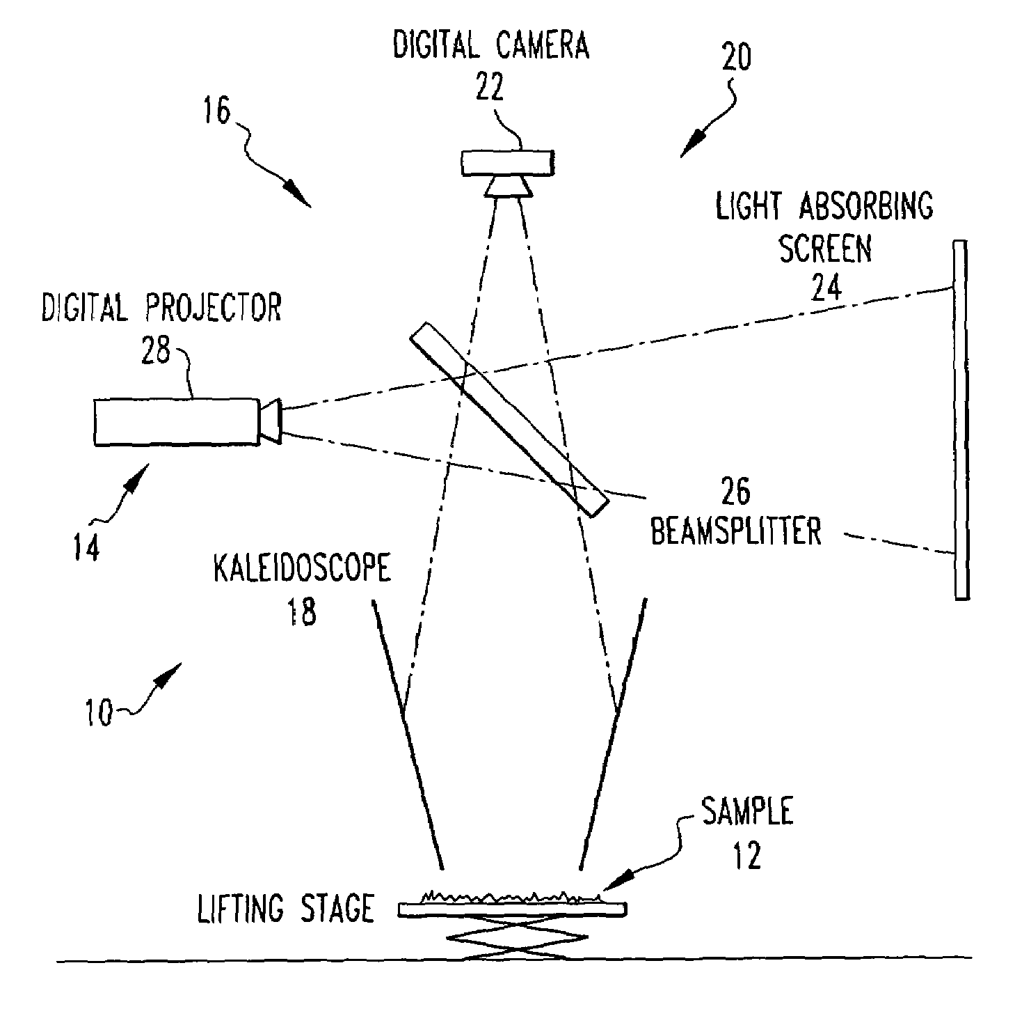
[0040]Referring now to the drawings wherein like reference numerals refer to similar or identical parts throughout the several views, and more specifically to FIG. 2 thereof, there is shown an apparatus 10 for determining a bidirectional reflectance distribution function of a subject 12. The apparatus 10 comprises a light source 14 for producing light. The apparatus 10 comprises means for measuring the bidirectional reflectance distribution function of the subject 12 from multiple locations simultaneously with the light.

[0041]Preferably, the measuring means 16 includes a kaleidoscope 18. The measuring means 16 preferably includes sensing means 20 for sensing the light from the subject 12. Preferably, the sensing means 20 includes a camera 22 which receives light from the subject 12. The camera 22 is positioned so a path of the light from the subject 12 and the light source 14 are merged.

[0042]The sensing means 20 preferably includes a light absorbing screen 24 which receives light f...


PUM

PropertyMeasurementUnit
vertical angleaaaaaaaaaa
vertical field of viewaaaaaaaaaa

Abstract

An apparatus for determining a bidirectional reflectance distribution function of a subject. In one embodiment, the apparatus includes a light source for producing light. The apparatus includes means for measuring the bidirectional reflectance distribution function of the subject from multiple locations simultaneously with the light. A method for determining a bidirectional reflectance distribution function of a subject.

Description

[0001]The present invention is a continuation-in-part of U.S. patent application No. 10 / 620,920 filed on Jul. 16, 2003, which claims priority from U.S. provisional application 60 / 396,697 filed on Jul. 17, 2002.[0002]This application claims the benefit of U.S. Provisional Application No.: Application No. 60 / 476,320 filing date Jun. 06, 2003FIELD OF THE INVENTION[0003]The present invention is related to determining a bidirectional reflectance distribution function of a subject. More specifically, the present invention is related to determining a bidirectional reflectance distribution function of a subject using a kaleidoscope.BACKGROUND OF THE INVENTION[0004]Much recent work in realistic image synthesis has focused on the use of actual data measurements of real-world surfaces and materials, both in the search for better data-driven reflectance models, and for direct use in image-based rendering techniques.[0005]The reflectance properties of a surface can be characterized by its Bidire...

Claims


Application Information

Patent Timeline
Patent Type & Authority Patents(United States)
IPC IPC(8): G01N21/47G01N21/55G02B
CPCG01N21/4795G01N2021/4711G01N21/55
Inventor HAN, JEFFERSON Y.PERLIN, KENNETH
Owner NEW YORK UNIV
Learn More