
Variable resistance devices and methods

a variable resistance and rubber technology, applied in the direction of adjustable resistors, thermistors with sliding contact, resisitors with positive temperature coefficient, etc., can solve the problem that the use of resistive rubber in variable resistance devices has been limited to relatively simple and specific applications

Inactive Publication Date: 2007-03-13
FOREST ASSETS II LIMITED LIABILITY +1
View PDF27 Cites 5 Cited by
  • Summary
  • Abstract
  • Description
  • Claims
  • Application Information

AI Technical Summary

Benefits of technology

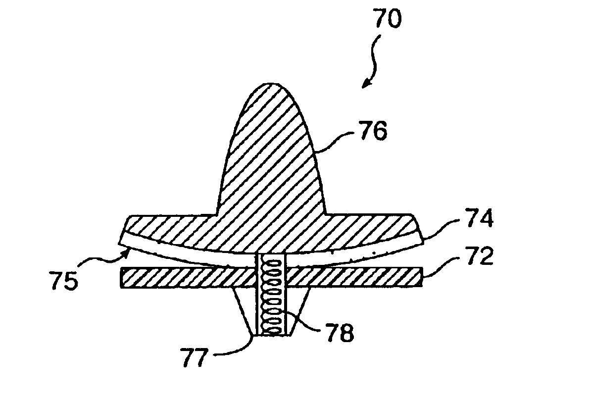
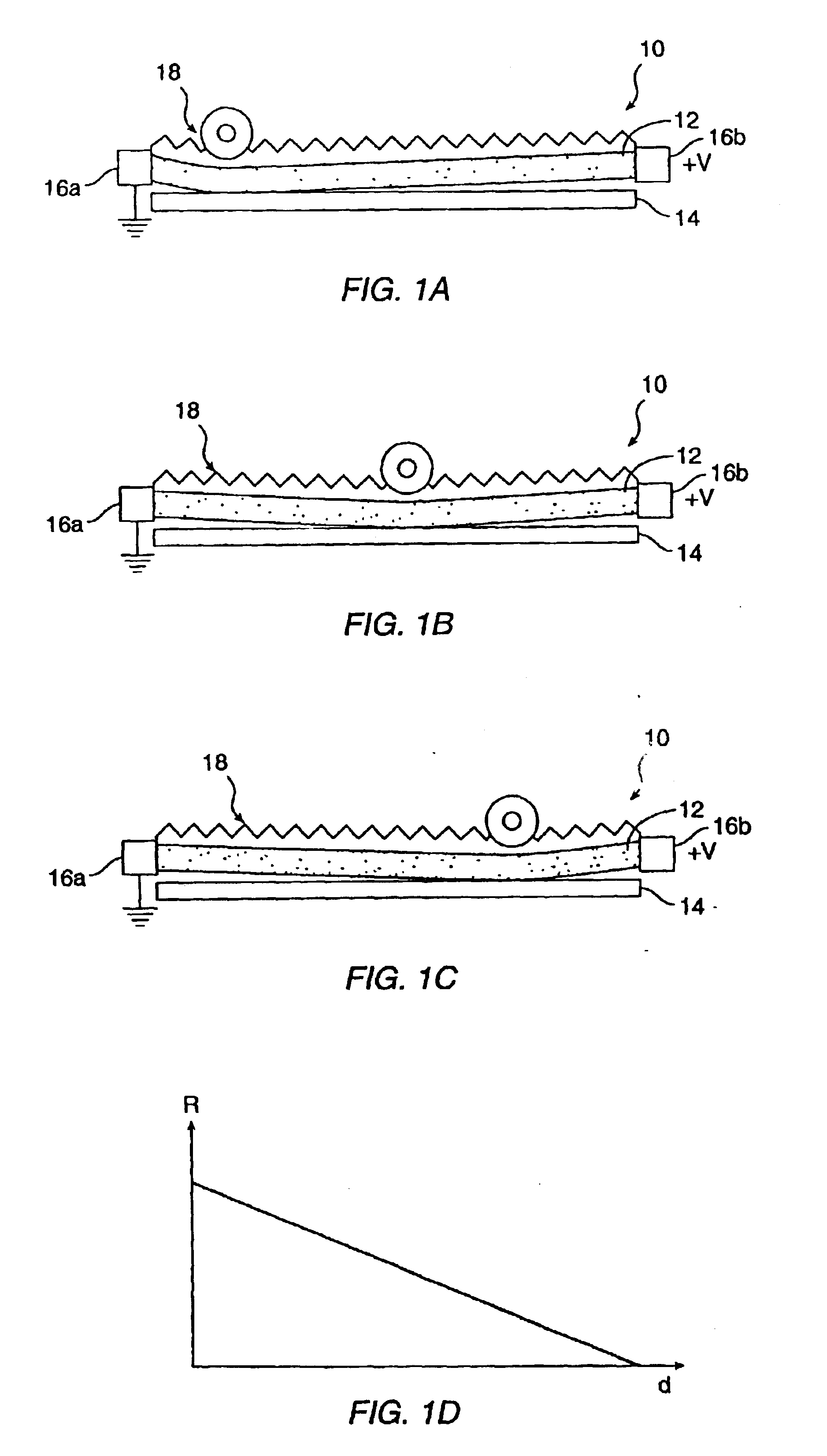
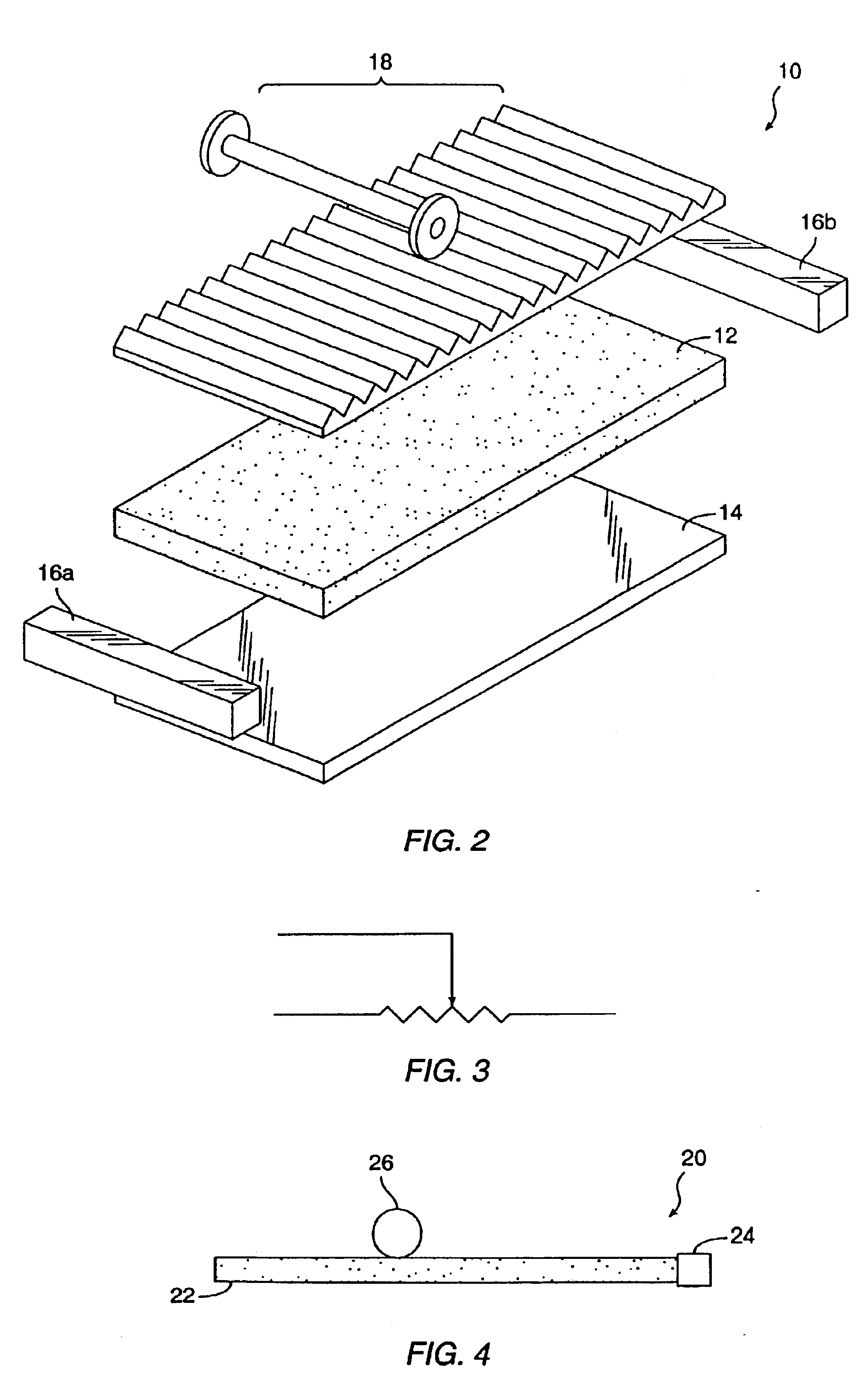
"The present invention relates to variable resistance devices that make use of the characteristics of resistive rubber materials. The invention provides a resistive member that includes a resistive resilient material, such as silicone or natural rubber, that is interspersed with electrically conductive materials like silver or copper. The resistance of the material is determined by the resistivity of the material and the length of the resistor. The resistance is proportional to the resistivity and the cross-sectional area perpendicular to the current flow. The invention also discusses the effective resistance of a resistive network formed with resistors that have different structures and geometries. The effective resistance is determined by the combination of a straight path resistance component and a parallel path resistance component. The invention provides a variable resistance device that includes a resistive member with a resistive surface for contacting the conductors, and the resistance between the conductors can be controlled by adjusting the distance between the contact locations. The technical effect of the invention is to provide a more accurate and reliable method for controlling resistance in a network of resistors."

Problems solved by technology

Heretofore, the use of resistive rubber in variable resistance devices has been limited to relatively simple and specific applications.

Method used


Image

  • Variable resistance devices and methods
  • Variable resistance devices and methods
  • Variable resistance devices and methods

Examples


Embodiment Construction

[0040]The variable resistance devices of the present invention include components made of resistive resilient materials. An example is a low durometer rubber having a carbon or a carbon-like material imbedded therein. The resistive resilient material advantageously has a substantially uniform or homogeneous resistivity, which is typically formed using very fine resistive particles that are mixed in the rubber for a long period of time in the forming process. The resistive property of resistive resilient material is typically measured in terms of resistance per a square block or sheet of the material. The resistance of a square block or sheet of a resistive resilient material measured across opposite edges of the square is constant without regard to the size of the square. This property arises from the counteracting nature of the resistance-in-series component and resistance-in-parallel component which make up the effective resistance of the square of material. For instance, when two...


PUM

PropertyMeasurementUnit
resistanceaaaaaaaaaa

Abstract

A method of providing a variable resistance from a resistive member including a resistive resilient material comprises electrically coupling a first conductor with the resistive member at a first contact location over a first contact area; and electrically coupling a second conductor with the resistive member at a movable second contact location over a second contact area. The second contact location is movable relative to the resistive member to change the second contact location between the second conductor and the resistive member, the first contact location and the movable second contact location being spaced from one another by a distance. The method further comprises changing at least one of the first location, the second location, the first contact area, and the second contact area to produce a change in resistance in the resistive member, measured between the first conductor at the first contact location and the second conductor at the second contact location, as the resistive member deforms along the second conductor.

Description

[0001]This application is a continuation-in-part of U.S. patent application Ser. No. 10 / 060,046, filed Jan. 28, 2002, now abandoned, which is a divisional application of U.S. patent application Ser. No. 09 / 318,183, filed May 25, 1999, now U.S. Pat. No. 6,404,323, the disclosures of which are incorporated herein by reference.BACKGROUND OF THE INVENTION[0002]This invention relates generally to variable resistance devices and methods and, more particularly, to devices and methods which employ resistive resilient materials including resistive rubber materials for providing variable resistance.[0003]Variable resistance devices have been used in many applications including sensors, switches, and transducers. A potentiometer is a simple example of a variable resistance device which has a fixed linear resistance element extending between two end terminals and a slider which is keyed to an input terminal and makes movable contact over the resistance element. The resistance or voltage (assumi...

Claims


Application Information

Patent Timeline
Patent Type & Authority Patents(United States)
IPC IPC(8): H01C10/06
CPCH01C10/06H01C10/12H01C10/305H01C10/38Y10T29/49082Y10T29/49117Y10T29/49085Y10T29/49101
Inventor SCHRUM, ALLAN E.ROGERS, MICHAEL D.
Owner FOREST ASSETS II LIMITED LIABILITY
Learn More