
Ventricular assist system secondary impeller

a technology of assist system and secondary impeller, which is applied in the field of medical science, can solve the problems of undesirable and potentially life-threatening for patients, heat and/or stagnation of blood,

Inactive Publication Date: 2007-03-13
HORVATH DAVID +2
View PDF5 Cites 35 Cited by
  • Summary
  • Abstract
  • Description
  • Claims
  • Application Information

AI Technical Summary

Benefits of technology

[0010]One advantage of the present invention is a blood pump with a single moving part with no seal between the motor and blood compartments.
[0011]Another advantage resides in avoiding problems associated with drive shaft interfaces.
[0012]Another advantage is the creation of blood flow and wash patterns that avoid the formation of blood element depositions.
[0013]Still further benefits and advantages of the present invention will become apparent to those skilled in the art upon a reading and understanding of the preferred embodiments.

Problems solved by technology

A potential problem with this system is that the blood can become heated and / or stagnant, and partially solidify by forming a thrombus or heat coagulation of blood proteins on the stator housing surface or on the secondary impeller of the motor rotor in the inverted fluid film bearing assembly.
Such a situation is undesirable and potentially life-threatening to the patient who is dependant on the proper function of such a device.

Method used


Image

  • Ventricular assist system secondary impeller
  • Ventricular assist system secondary impeller
  • Ventricular assist system secondary impeller

Examples


Embodiment Construction

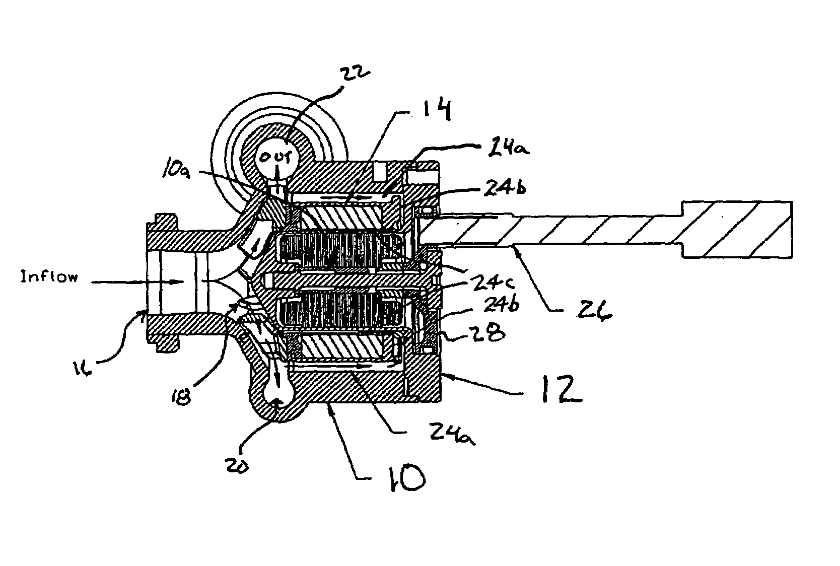
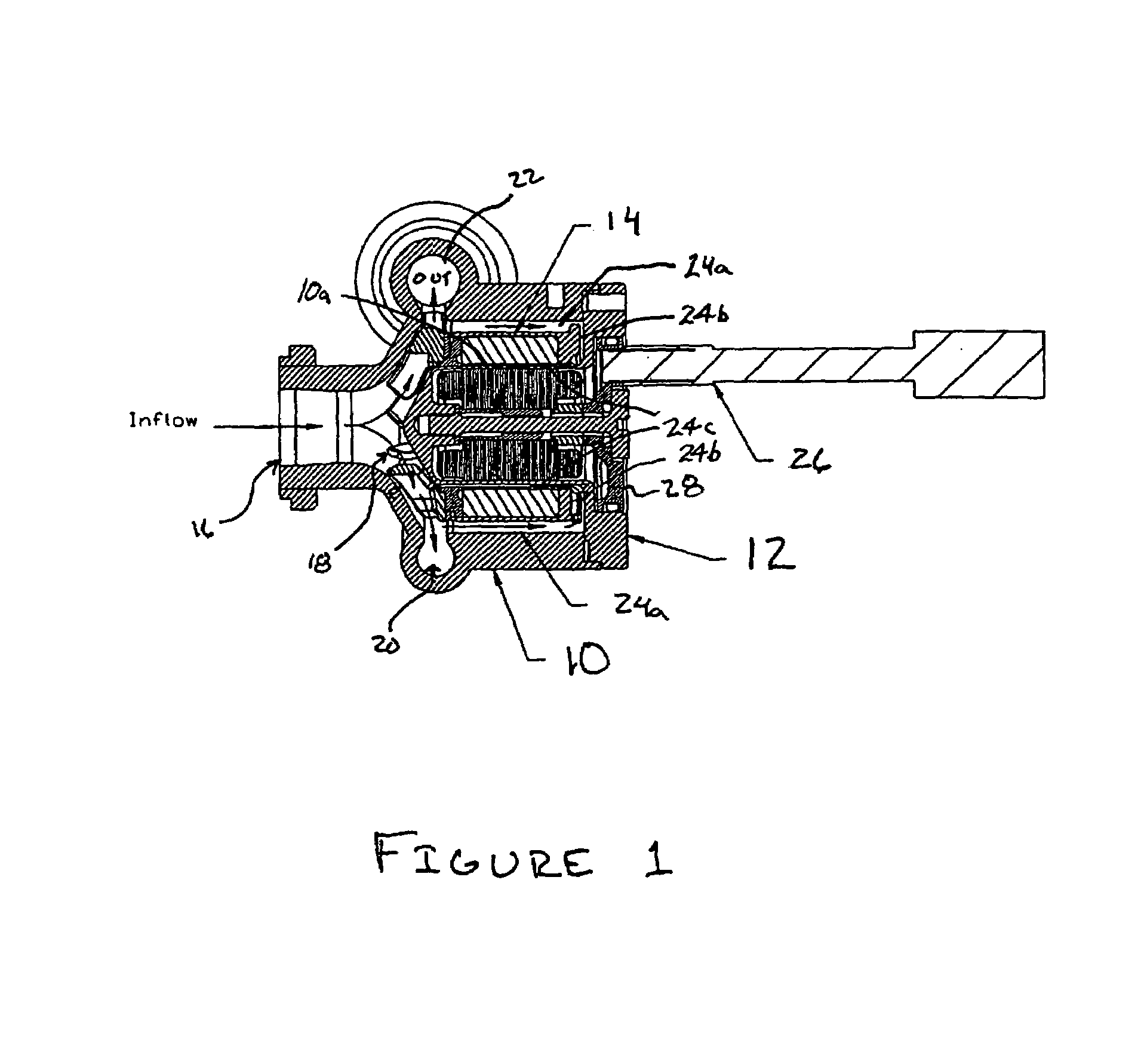
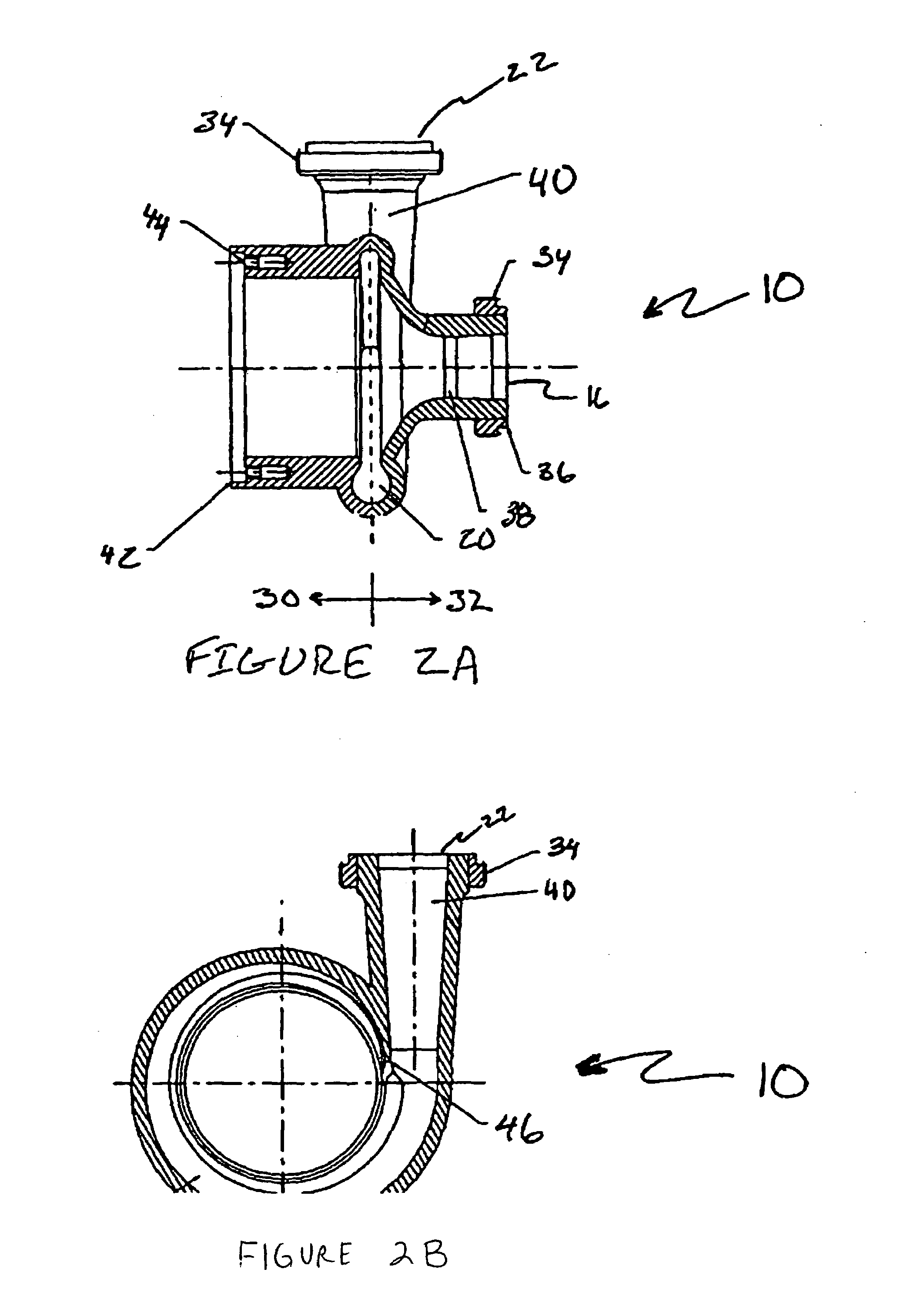
[0023]With reference to FIG. 1, a centrifugal flow blood pump comprises three primary subassemblies, namely a volute housing assembly 10, a stator assembly 12, and a rotating assembly or rotor 14. Blood from a patient flows into an inlet port 16 of the blood pump. Arrows (unnumbered) indicate the direction of travel of the blood through the pump in the preferred embodiment. The blood specifically by primary impeller 18. The blood proceeds around the volute housing, first entering a volute channel 20 and a primary portion exiting the pump via a discharge port 22.

[0024]A small portion of the blood flows into a second channel or passage 24, specifically a first passage portion 24a that extends axially from a rear face of the primary impeller and is radially interposed between the rotor and a post formed by an axial extension 10a of the stator housing that protrudes into a pump chamber defined in the volute housing. As is well known, the chamber is in fluid communication with the inlet ...


PUM


Abstract

In a centrifugal flow blood pump, usable in left ventricular assist applications, blood is pumped from an inlet (16) to an outlet (22) by a primary impeller (18). A portion of the blood that enters the pump follows a secondary channel (24) where a secondary impeller (70) routes the blood to lubricate a bearing between an impeller assembly (14) and a post formed by a component of the pump housing. The unique shape of the secondary impeller (70) prevents blood stagnation and provides for a well-washed fluid bearing.

Description

FEDERAL RESEARCH STATEMENT[0001]The U.S. Government may have certain rights in this invention pursuant to contract number N01-HV-58159 awarded by the U.S. National Heart, Lung and Blood Institute of the National Institutes of Health.BACKGROUND OF THE INVENTION[0002]The present invention relates to the medical arts. It finds particular application in cardiac assist technologies using rotodynamic blood pumps, also known as left ventricular assist devices (LVAD) in assisting patients with failing hearts and will be described with particular reference thereto. It is to be appreciated that the present invention is also applicable to other types of pumps, and is not limited to the aforementioned application.[0003]Rotodynamic pumps (axial flow, mixed flow, and centrifugal) have prospective applications in cardiac assist technologies. A typical cardiac assist system includes the blood pump itself, electric motor (usually a brushless DC motor integrated into the pump), drive electronics, mic...

Claims


Application Information

Patent Timeline
IPC IPC(8): A61M1/10F04D7/02F04D29/046F04D13/06F04D13/14F04D29/047F04D29/22F04D29/24
CPCA61M1/101A61M1/1017F04D29/2211F04D13/0646A61M60/824A61M60/422A61M60/148A61M60/232A61M60/419A61M60/812A61M60/178
Inventor HORVATH, DAVIDGOLDING, LEONARD A. R.SMITH, WILLIAM A.
Owner HORVATH DAVID
Learn More