
Fabrication of interleaved metallic and intermetallic composite laminate materials

a technology of composite laminate materials and interleaved metals, which is applied in the field of fabrication of interleaved metallic and intermetallic composite laminate materials, can solve the problems of limiting its penetration, forming fracture cracks in the plane of composite laminate materials, and not evenly forming in either (i) space or (ii) tim

Inactive Publication Date: 2007-03-13
RGT UNIV OF CALIFORNIA
View PDF8 Cites 71 Cited by
  • Summary
  • Abstract
  • Description
  • Claims
  • Application Information

AI Technical Summary

Benefits of technology

[0044]Moreover, and importantly, the tough metal layers serve to limit the cracking and fracturing of the hard intermetallic regions, or layers, in the first place (i) by blunting the propagation of cracks and fractures at the boundaries between the metal layers and intermetallic regions, and (ii) by channeling such cracks and fractures of the intermetallic regions as do occur in directions orthogonal to the axis of projectile impact (where they do little to promote projectile penetration)—instead of along the axis of impact (where penetration might be assisted). In simple terms, fracture cracks are hard to form in the composite laminate material of the present invention, and those that do form so form in the wrong directions to effectively remove (hard) fractured material from in front of an impinging projectile.
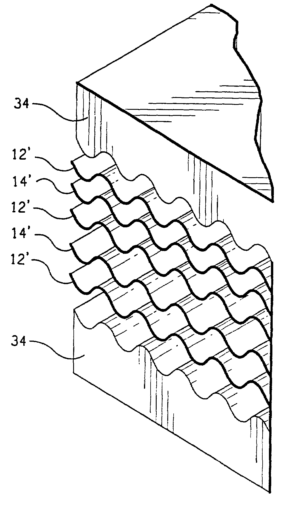
[0048]The propensity of the composite laminate material to “turn” the penetrating projectile can be still further improved if the laminate material is corrugated, in which mode the laminate material may be readily economically fabricated. For the rare case that the projectile hits centrally in the trough of a corrugation, it is possible to back one layer of corrugated armor with another that is offset, thus making it effectively impossible that a penetrating projectile should not be subject to significant flight-direction-distorting forces.1. Method of Producing Laminate Composite Materials, Especially as are Useful for Hard Armor, in Accordance with the Present Invention
[0077]The corrugated composite laminate material enjoys all the normal mechanical and strength advantages of corrugation. In other words, it may be capable of better supporting a load aligned with axis of corrugations in the plane of the material without buckling or bending. To this extent the utility of the material for construction, including for load-bearing walls and the sides of armored vehicles, is enhanced. Equally importantly, the corrugations help to turn the path of an impacting projectile. To account for the statistically small probability that the projectile should hit centrally in the trough of a corrugation, it is possible to back one panel of corrugated armor with another, offset, panel. If structural strength is desired in two perpendicular directions in the plane of a composite laminate material of the present invention, then corrugated panels of the material having their corrugations running in one direction may be alternated with other panels of the material having their corrugations running at a 90° angle.
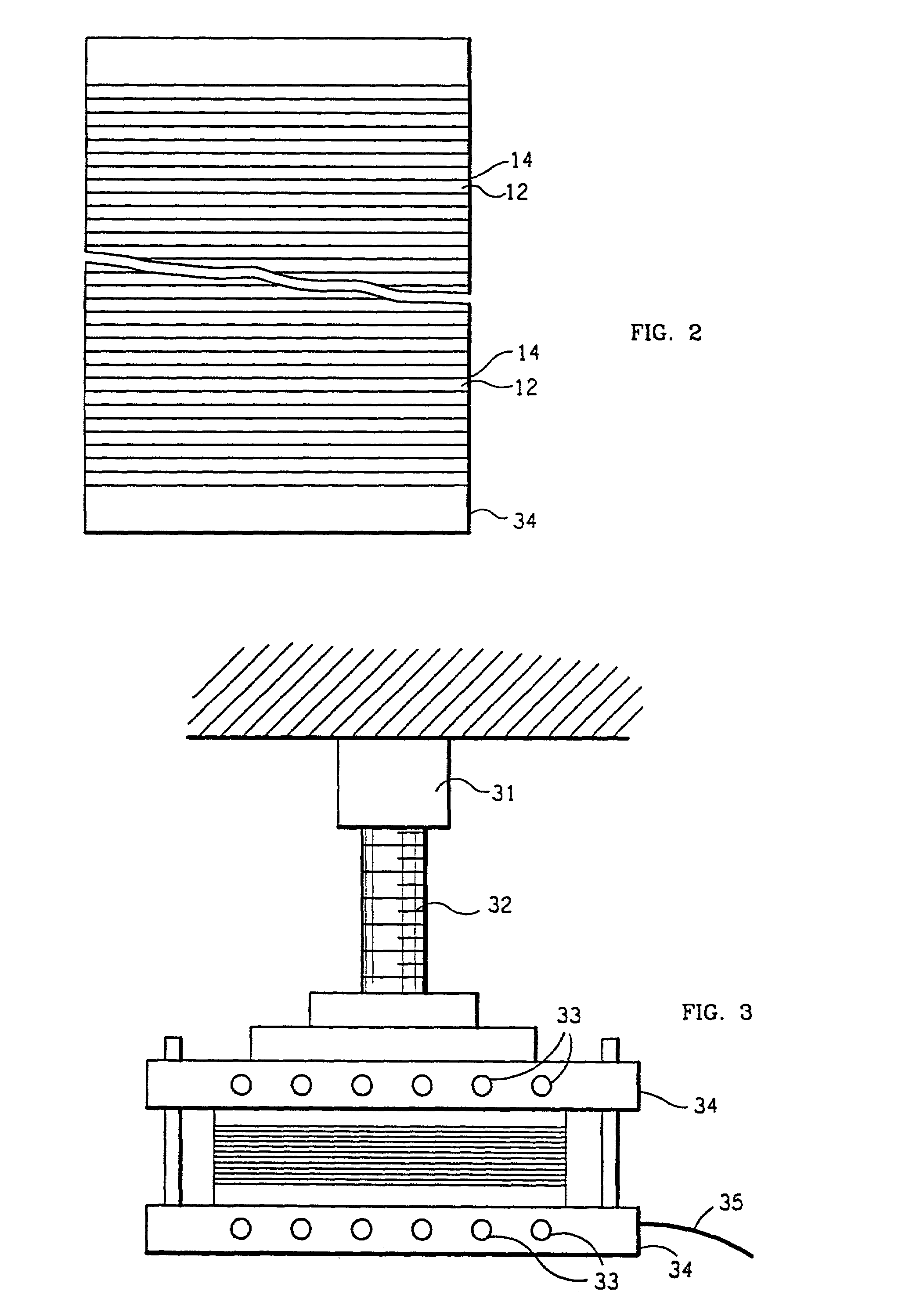
[0081]The stacked metal films are conventionally heated to a modest 600–800° C. while being pressured at a modest 1–10 megapascals, normally in the open air in a load frame. The composite material thus formed has (i) very tough first-metal layers separated by (ii) very hard intermetallic regions consisting of a compound of the first and second metals. The material density of, typically, 3 to 4.5 grams / cubic centimeter is both lightweight and strong to serve as armor.

Problems solved by technology

The confinement makes that any such fragmentation of the hard intermetallic layer by a high-energy impinging projectile as will inevitably occur will be poorly serve to displace the resulting hard fragments from in front of the projectile, forcing the projectile to interact with these hard fragments and limiting its penetration.
Moreover, the fracture cracks that form in the plane of the composite laminate material (or armor), and sideways to the path of the impinging projectile (instead of ahead of the projectile), do not evenly so form in either (i) space or (ii) time.
This means that those crooked, non-straight, fracture cracks that do form do not identically so form over time.

Method used


Image

  • Fabrication of interleaved metallic and intermetallic composite laminate materials
  • Fabrication of interleaved metallic and intermetallic composite laminate materials
  • Fabrication of interleaved metallic and intermetallic composite laminate materials

Examples


Embodiment Construction

[0094]Although specific embodiments of the invention will now be described with reference to the drawings, it should be understood that such embodiments are by way of example only and are merely illustrative of but a small number of the many possible specific embodiments to which the principles of the invention may be applied. Various changes and modifications obvious to one skilled in the art to which the invention pertains are deemed to be within the spirit, scope and contemplation of the invention as further defined in the appended claims.

1. Theory of the Performance of Armor Made From the Composite Laminate Material of the Present Invention

[0095]The instant theory of the performance of the composite laminate material of the present invention when employed as armor must be held to be hypothetical, and to be only a best present estimate of what transpires when a projectile impinges upon the composite laminate material. It is possible to estimate the hardness of the embedded interm...


PUM


Abstract

Typically 20–40 films of a tough first metal, normally 0.1–1.0 mm thick films of titanium, nickel, vanadium, and / or steel (iron) and alloys thereof, interleaved with a like number of films of a second metal, normally 0.1–1.0 mm thick films of aluminum or alloys thereof, are pressed together in a stack at less than 6 MPa and normally at various pressures 2–4 MPa while being gradually heated in the presence of atmospheric gases to 600–800° C. over a period of, typically, 10+ hours until the second metal is completely compounded; forming thus a metallic-intermetallic laminate composite material having (i) tough first-metal layers separated by (ii) hard, Vickers microhardness of 400 kg / mm2+, intermetallic regions consisting of an intermetallic compound of the first and the second metals. The resulting composite material is inexpensive, lightweight with a density of typically 3 to 4.5 grams / cubic centimeter, and very hard and very tough to serve as, among other applications, lightweight armor. Upon projectile impact (i) the hard intermetallic, ceramic-like, layers are confined by the tough metal layers while (ii) cracking and fracturing is blunted and channeled in directions orthogonal to the axis of impact.

Description

REFERENCE TO A RELATED PATENT APPLICATION[0001]The present application is a divisional of U.S. patent application Ser. No. 09 / 130,722 of the same name filed on Aug. 6, 1998, to the same inventor; which application issued on Mar. 19, 2002 as U.S. Pat. No. 6,357,332.[0002]This invention was made by support of the U.S. Government under Contract No. ARO MURIADAAHO-4-96-1-0376 acting through the United States Army Research Office. The U.S. Government has certain rights in this invention.BACKGROUND OF THE INVENTION[0003]1. Field of the Invention[0004]The present invention generally concerns (i) processes for making composite laminate materials from multiple sheets of thin metals; (ii) laminate composite materials so made; and (iii) uses of the laminate composite materials so made, particularly in lightweight armor.[0005]The present invention particularly concerns (i) processes for making in air in a heated load press composite laminate materials at large size and low cost, including in co...

Claims


Application Information

Patent Timeline
IPC IPC(8): F41A5/04F41H5/04
CPCF41H5/045Y10S428/911
Inventor VECCHIO, KENNETH
Owner RGT UNIV OF CALIFORNIA
Learn More