Jaw arm for compression tools

a technology of compression tools and jaw arms, which is applied in the field of compression tools, can solve the problems of difficult alignment process, high design cost, and difficult alignment, and achieve the effect of convenient alignment of inserts, convenient maintenance of inserts, and optimized support of inserts

Inactive Publication Date: 2007-03-13
EMERSON ELECTRIC CO
View PDF24 Cites 13 Cited by
  • Summary
  • Abstract
  • Description
  • Claims
  • Application Information

AI Technical Summary

Benefits of technology

[0006]In accordance with the present invention, a jaw arm for a compression tool is provided with a jaw insert which is pivotal relative to the jaw arm to facilitate alignment of the insert with a corresponding portion of a tube and coupling to be crimped through the use of a compression tool. More particularly, the jaw insert is removably mounted in a recess provided therefor in a jaw arm and is supported in the recess for pivotal displacement relative to the jaw arm about an insert axis extending transverse to the pivot axis of the jaw arm. Preferably, the insert and jaw arm recess have facially interengaging arcuate surfaces so as to optimize support of the insert during a compression operation. The insert can be manually displaced relative to the jaw arm so as to establish an approximate angular position of the insert relative to the jaw arm prior to initiating a compression operation and, preferably, a biasing arrangement is provided between the jaw arm and insert which creates a torque requirement for pivoting the insert and, thus, promotes maintaining the insert in the adjusted position. Such prepositioning is of particular advantage when the location of the joint to be crimped cannot be accessed with the drive mechanism perpendicular to the axes of the pipe and coupling components to be crimped. In any event, even if the location for the compression operation is such that the drive mechanism and thus the jaw arms can be positioned perpendicular to the axes of the pipe and coupling to be joined, the pivotal capability of the insert advantageously provides for the pair of inserts on the arms of a jaw set to be self-aligning relative to the coupling components and to each other as the inserts are moved into place on opposite sides of the coupling components. Therefore, even if the operator does not have the drive mechanism exactly perpendicular to the axes of the coupling components, proper alignment of the inserts is achieved and, accordingly, proper crimping of the coupling components is achieved.
[0007]In accordance with another aspect of the invention, the opposed jaw inserts on the jaw arm members of a jaw set are provided with an arrangement for interengagement with one another during initial positioning and movement of the inserts into the crimping positions thereof to promote alignment of the inserts with one another throughout the compression operation. Such alignment further promotes obtaining a proper crimp of the pipe and coupling components.
[0009]A further advantage achieved in accordance with the present invention is the ability to selectively use a number of different inserts which are accommodated in the jaw recess and which provide compression surface contours for different sizes and / or shapes of pipes and couplings.
[0010]It is accordingly an outstanding object of the present invention to provide a jaw arm member for a compression tool with a jaw insert pivotal relative thereto to accommodate alignment of the insert with a pipe and coupling during crimping thereof.

Problems solved by technology

Failure to properly align the jaw recesses with the pipe and coupling can result in crushed fitting, or improper crimping of the pipe and coupling which can lead to leakage when the line being installed is placed in use, such as for delivering liquid under pressure.
Alignment is somewhat difficult to achieve under any circumstances in that the operator of the compression tool must support the latter with the jaws open, engage the jaws about a pipe and coupling, and then actuate the drive mechanism to complete the compression process.
Therefore, as will be appreciated from the aforementioned patent to Nghiem, the size and weight of the drive mechanism and jaw assembly add to the difficulty in obtaining and maintaining proper alignment between the jaw recesses, pipe and coupling, and the alignment process is made more difficult if the component parts to be compressed are located above the operator's head and / or in areas that are difficult to gain access to.
It will be appreciated, therefore, that the design is expensive to construct and that use thereof is cumbersome and time-consuming and, in many cases, may require two operators to achieve the mounting of the attachment and the connection thereof to the jaw arms of the jaw set.

Method used


Image

  • Jaw arm for compression tools
  • Jaw arm for compression tools
  • Jaw arm for compression tools

Examples


Embodiment Construction

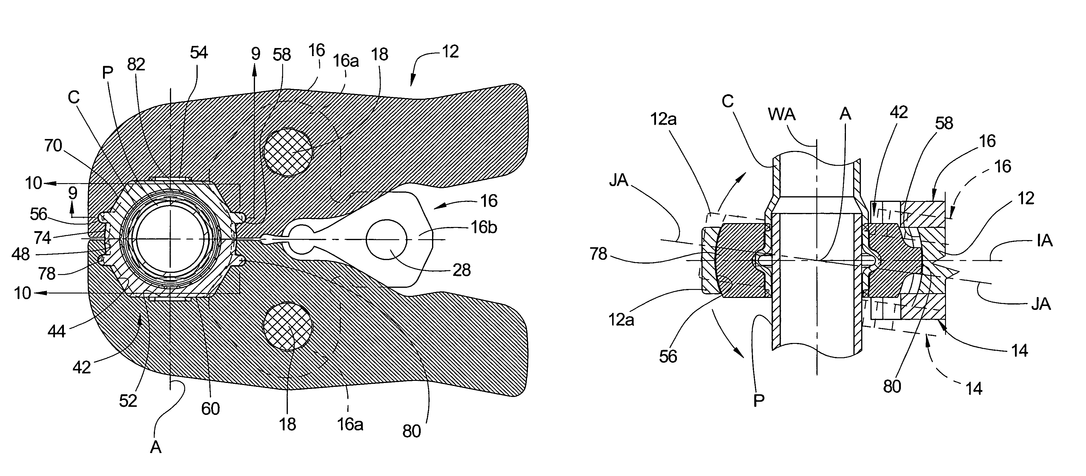
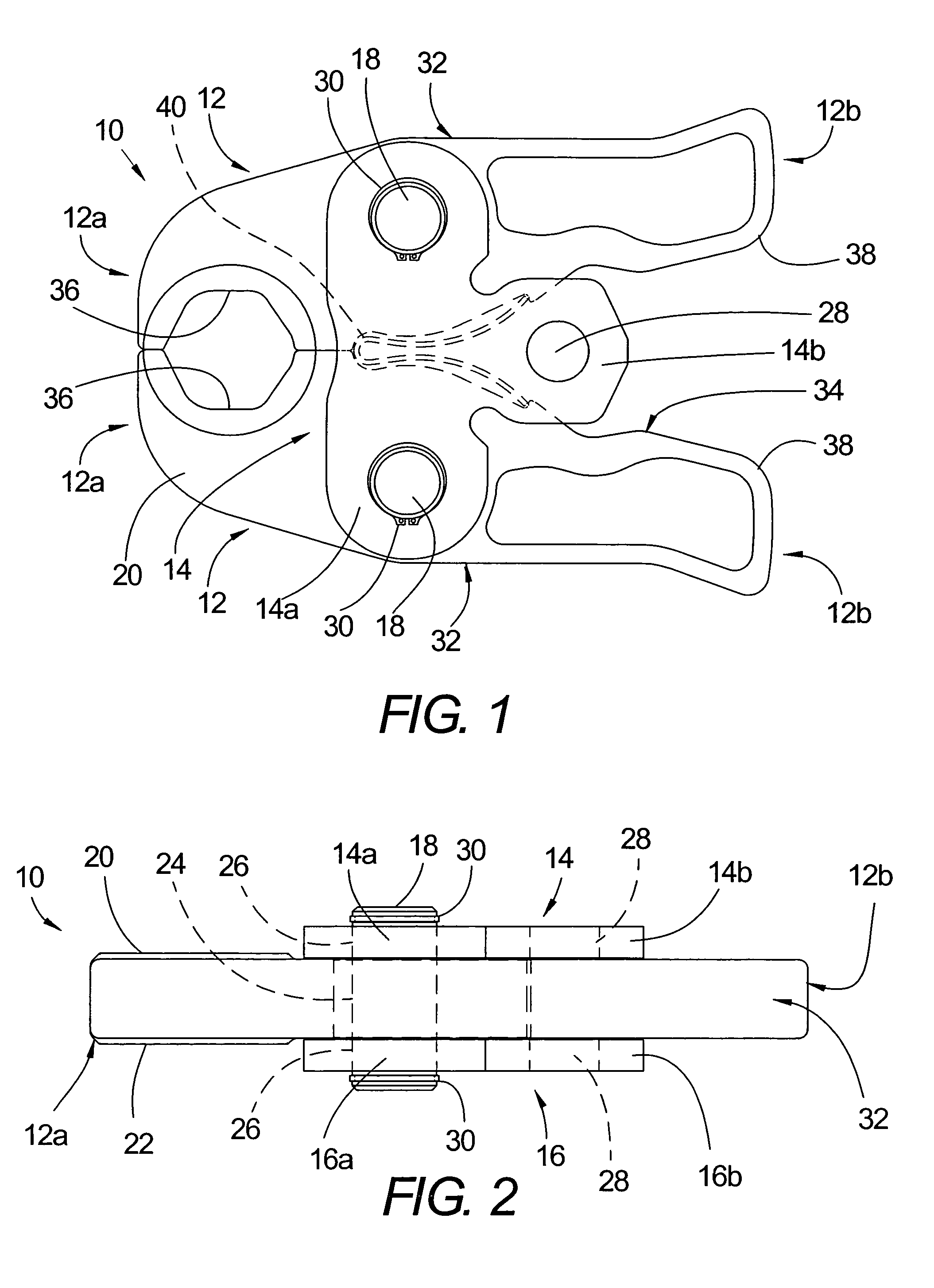
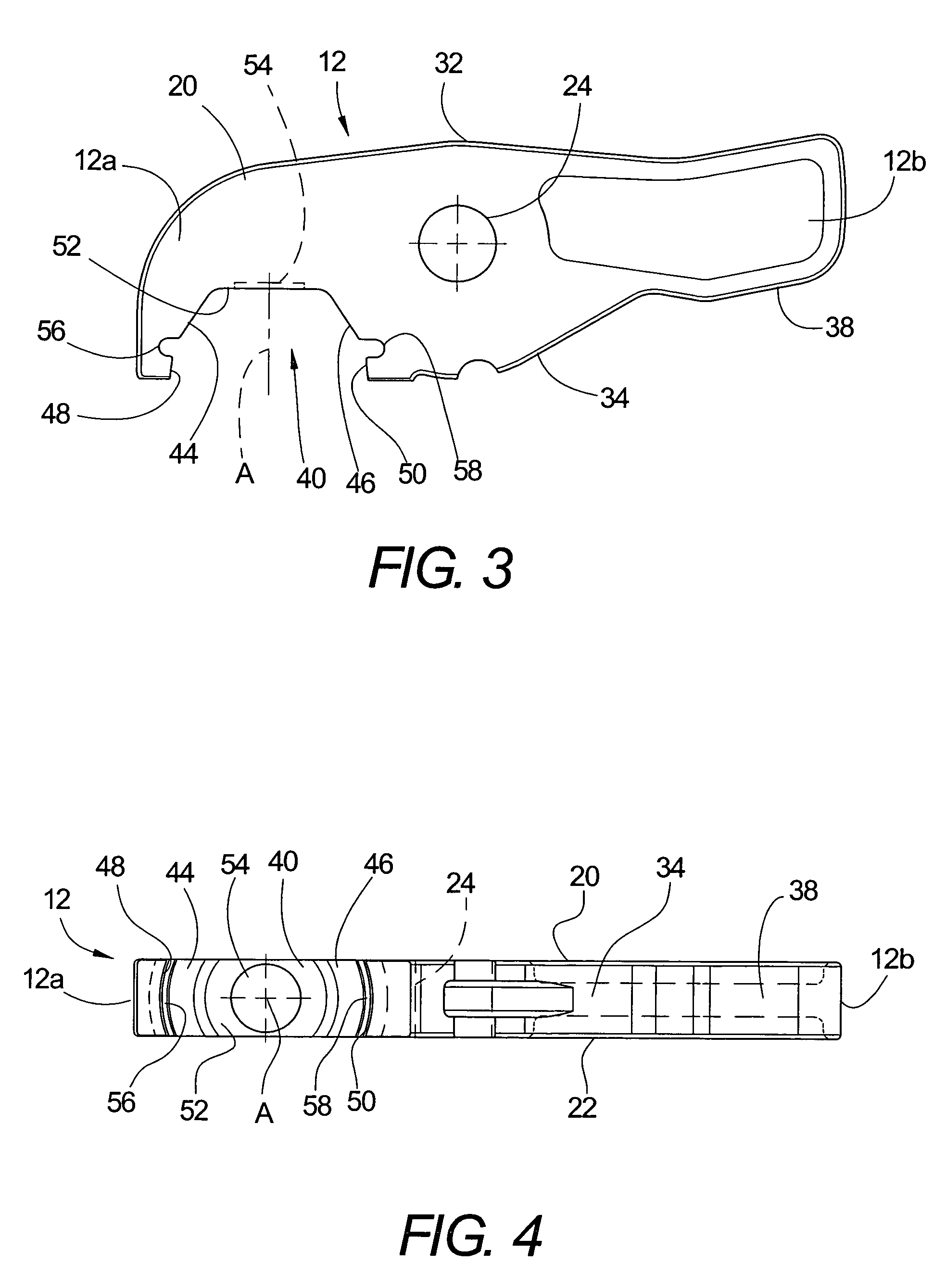
[0039]Referring now in greater detail to the drawings, wherein the showings are for the purpose of illustrating preferred embodiments of the invention only and not for the purpose of limiting the invention, FIGS. 1 and 2 illustrate a prior art jaw set 10 comprising a pair of jaw arm members 12 which are mounted, in the orientation shown in FIGS. 1 and 2, between top and bottom side plates 14 and 16, respectively, by a corresponding pivot or bearing pin 18. Each of the jaw arm members has a top side 20, a bottom side 22, and a pin opening 24 therethrough for receiving the corresponding pin 18. Side plates 14 and 16 are generally T-shaped and include laterally opposite sides 14a and 16a, respectively, which are provided with aligned holes 26 for receiving the outer ends of the corresponding pin 18. Side plates 14 and 16 further include rear ends 14b and 16b, respectively, which are provided with aligned openings 28 therethrough which are adapted to receive a mounting pin by which the ...


PUM

PropertyMeasurementUnit
angleaaaaaaaaaa
displacementaaaaaaaaaa
widthaaaaaaaaaa

Abstract

A jaw arm for a compression tool has a jaw recess at one end and a jaw insert is supported in the recess for pivotal displacement relative thereto about an insert axis. A compression tool comprises a pair of parallel spaced apart side plates, and a pair of the jaw arms pivotally mounted between the plates. The pivotal inserts are self-aligning with respect to a pipe and coupling to be crimped together and provide for use of the compression tool in areas with limited accessibility.

Description

BACKGROUND OF THE INVENTION[0001]This invention relates to the art of compression tools for joining pipes and couplings and, more particularly, to improvements in connection with the pivotal jaw arm members for a compression tool.[0002]Compression tools for joining tubes or pipes and coupling components are well known as shown, for example, in U.S. Pat. No. 6,035,775 to Nghiem and U.S. Pat. No. 6,434,998 to Amherd. Such tools include a compression jaw set removably mounted on a drive mechanism by which the jaw arms of the set are displaced into compression about a pipe and coupling to join the latter. The jaw set is comprised of a pair of jaw arm members pivotally mounted between a pair of side plates and having inwardly open, opposed jaw recesses at one end and laterally inwardly facing cam surfaces at the opposite ends. The jaw arms are pivotal about pins located in openings through the jaw arms between the opposite ends thereof, and the jaw set is mountable on the drive mechanism...

Claims


Application Information

Patent Timeline
Patent Type & Authority Patents(United States)
IPC IPC(8): B21D39/04
CPCB21D39/046B25B27/10Y10T29/5367
Inventor BOWLES, RICHARD R.HAMM, JAMES E.
Owner EMERSON ELECTRIC CO
Why Eureka
Try Eureka