Electromagnetic transducer and portable communication device
a transducer and electromagnetic technology, applied in the field of electromagnetic transducers, can solve the problems that low frequency signals such as audio signals cannot be reproduced by the conventional electromagnetic transducers
- Summary
- Abstract
- Description
- Claims
- Application Information
AI Technical Summary
Benefits of technology
Problems solved by technology
Method used
Image
Examples
example 1
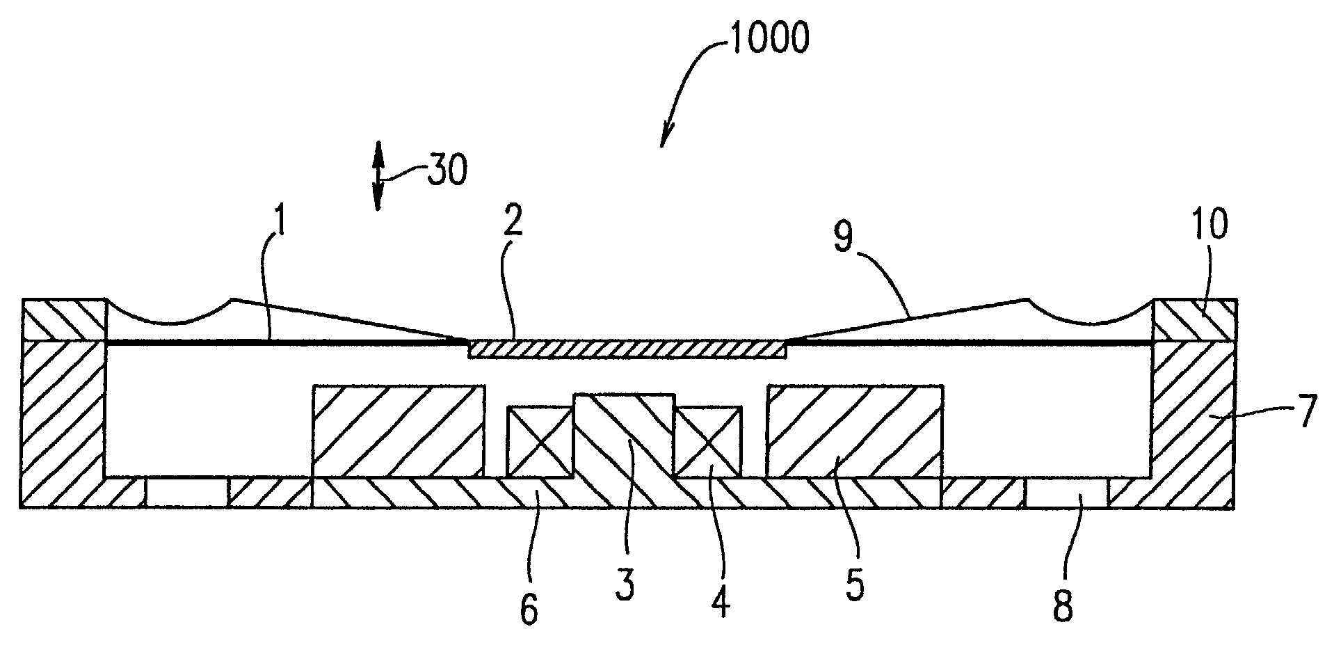
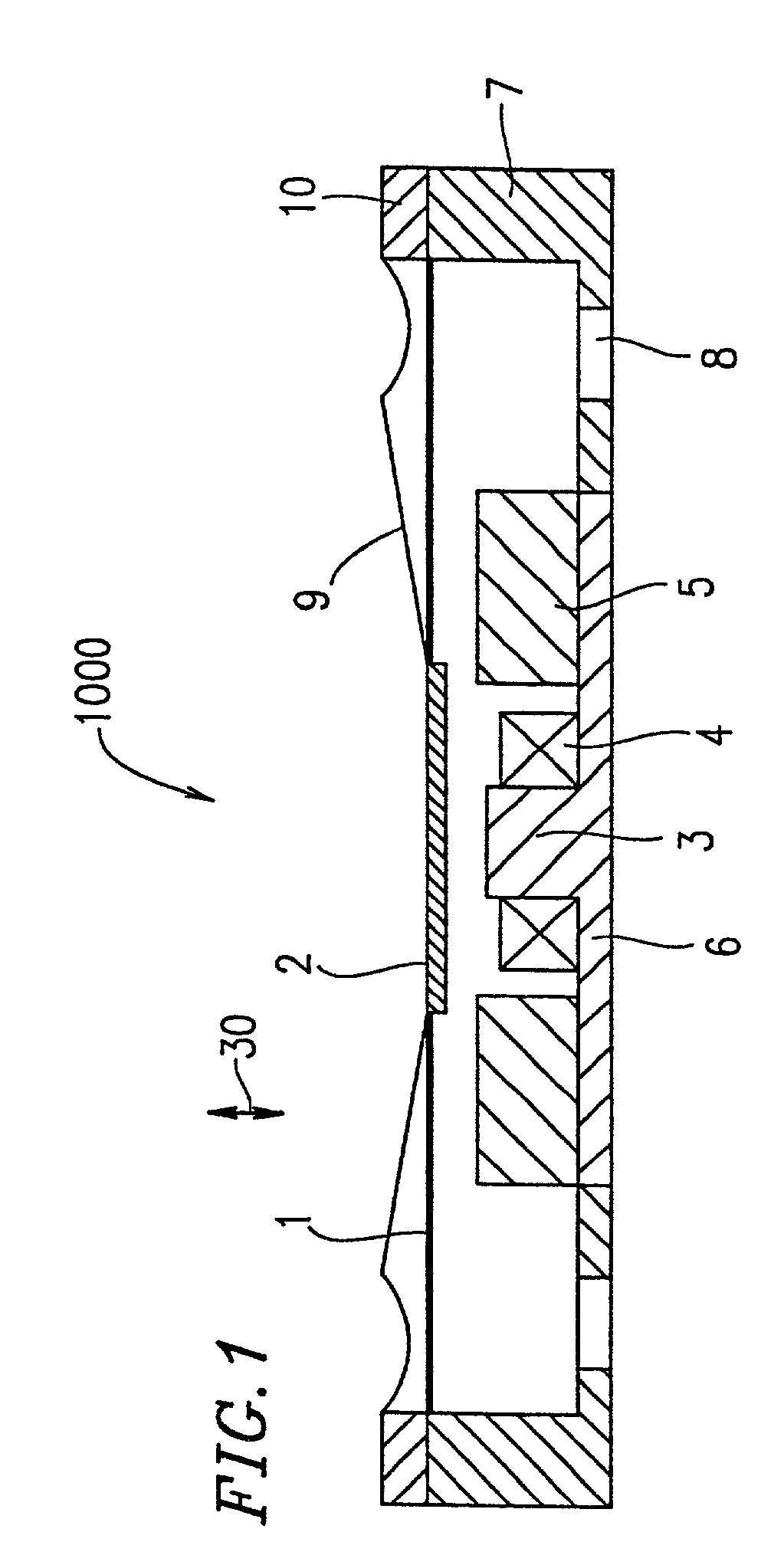
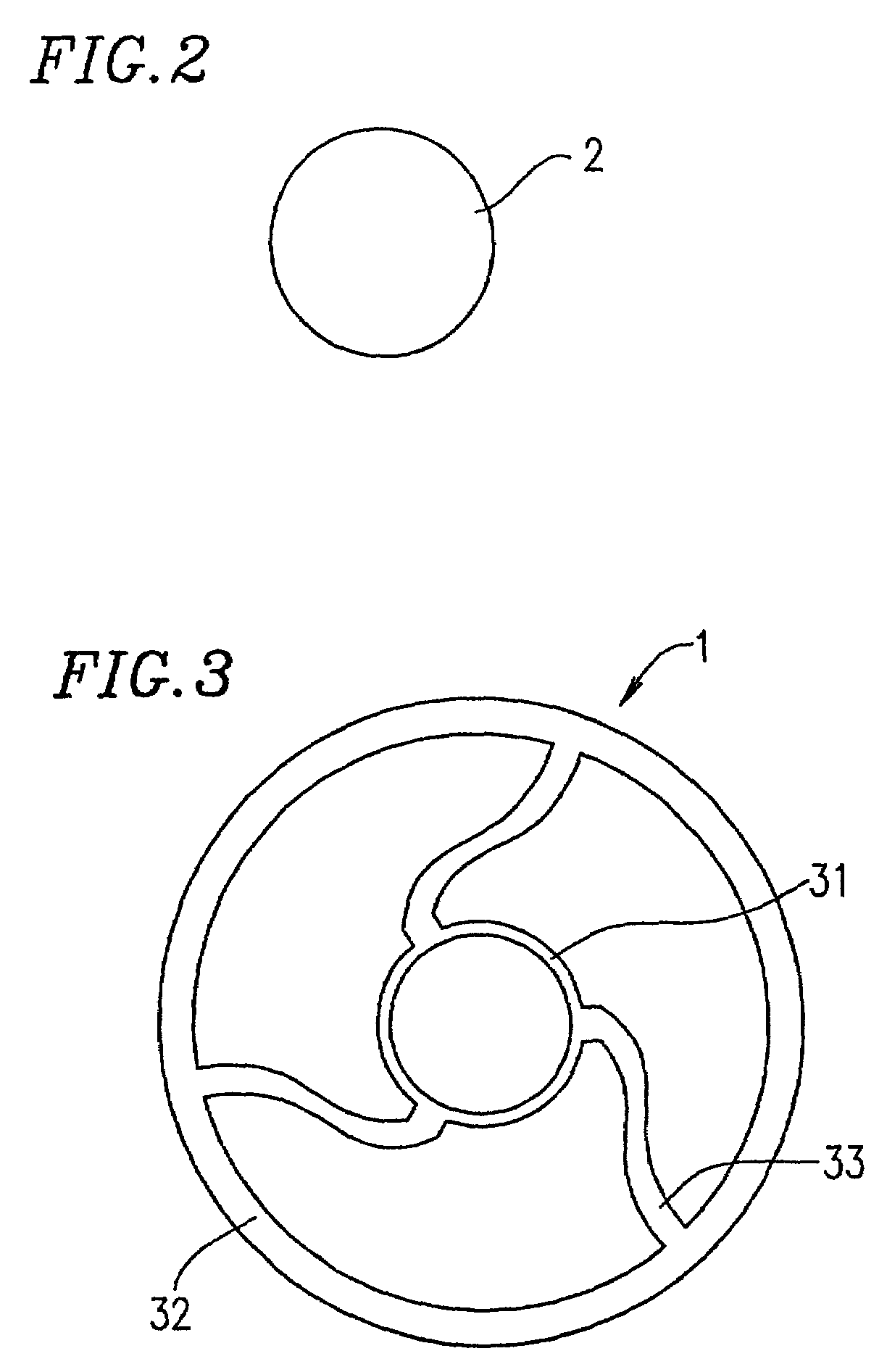
[0039]An electromagnetic transducer 1000 according to Example 1 of the present invention will be described with reference to FIGS. 1, 2 and 3.
[0040]FIG. 1 is a cross-sectional view showing the electromagnetic transducer 1000. The electromagnetic transducer 1000 includes a disk-shaped yoke 6, a cylindrical housing 7 surrounding the disk-shaped yoke 6, a center pole 3 provided in a central portion of the yoke 6, a coil 4 wound around the center pole 3, an annular magnet 5 spaced from the outer periphery of the coil 4, a suspension 1 supported by the housing 7 in such a manner as to be able to vibrate, a magnetic member 2 provided in a central portion of the suspension 1, a cylindrical spacer 10 provided on the housing 7, and a diaphragm 9 supported by the spacer 10 in such a manner as to be able to vibrate.
[0041]The central portion of the diaphragm 9 is connected with the suspension 1. An appropriate interspace is maintained between the coil 4 and the inner periphery of the annular ma...
example 2
[0055]An electromagnetic transducer 1100 according to Example 2 of the present invention will be described with reference to FIGS. 4 and 5.
[0056]FIG. 4 is a cross-sectional view showing the electromagnetic transducer 1100. The electromagnetic transducer 1100 includes a coil 4, a yoke 6, a housing 7, an air hole 8 and a spacer 10 which are the same as those of the electromagnetic transducer 1000 of FIG. 1.
[0057]FIGS. 5A, 5B and 5C are plan views of elements of the electromagnetic transducer 1100. As shown in these figures, the electromagnetic transducer 1100 further includes a annular magnetic member 12 having an opening provided in a central portion thereof, a suspension 11, a diaphragm 19, a center pole 13 having a shape which enables the center pole 13 to be inserted into the opening, a cover 20 covering the opening, a magnet 25 having a hollow portion, and a thin magnetic plate 15 provided in the hollow portion of the magnet 25. The upper face of the center pole 13 is positioned ...
example 3
[0066]An electromagnetic transducer 1200 according to Example 3 of the present invention will be described with reference to FIGS. 6 and 7.
[0067]FIG. 6 is a cross-sectional view of the electromagnetic transducer 1200. A coil 4, a yoke 6, an air hole 8, a center pole 13, a thin magnetic plate 15 and a magnet 25 of the electromagnetic transducer 1200 are the same as those of the electromagnetic transducer 1100 of Example 2 in FIG. 4.
[0068]FIG. 7 is a plan view of a suspension 21 of the electromagnetic transducer 1200. Referring to FIGS. 6 and 7, the electromagnetic transducer 1200 further includes the suspension 21 into which a magnetic member 12′ is integrated, a cylindrical housing 27 supporting the suspension 21 by its periphery, and a diaphragm 29 which is an integral part of the cover 20′. The outer periphery of the diaphragm 29 is substantially identical to that of the suspension 21, so that the outer periphery of the diaphragm 29 matches that of the suspension 21 on the same pl...
PUM
 Abstract
Description
Claims
Application Information
 - R&D
- Intellectual Property
- Life Sciences
- Materials
- Tech Scout
- Unparalleled Data Quality
- Higher Quality Content
- 60% Fewer Hallucinations
Browse by: Latest US Patents, China's latest patents, Technical Efficacy Thesaurus, Application Domain, Technology Topic, Popular Technical Reports.
© 2025 PatSnap. All rights reserved.Legal|Privacy policy|Modern Slavery Act Transparency Statement|Sitemap|About US| Contact US: help@patsnap.com


