
Internet switch router

a router and switch technology, applied in the field of internet switch routers, can solve the problems of limited bandwidth, limited bandwidth, and limited scalability of bus-based routers, and achieve the effect of greater bandwidth and scalability

Inactive Publication Date: 2007-03-06
FUTUREWEI TECH INC
View PDF41 Cites 43 Cited by
  • Summary
  • Abstract
  • Description
  • Claims
  • Application Information

AI Technical Summary

Benefits of technology

The present invention provides a way to use crossbar-based routers to route data packets in the internet backbone with greater bandwidth and scalability. By implementing the router as a multi-hop network, the invention allows for non-blocking communication between inputs and outputs. The fabric of fabric links and fabric routers provides data communication between internet links through one or more hops through the fabric. The invention also includes a line interface to each internet link to identify output internet links through an internet routing protocol and a fabric routing protocol to determine the routing path through the fabric. The invention further includes an arbitration to assign virtual channels to output fabric links and flow control to manage data flow through the fabric. Overall, the invention allows for efficient routing and flow control in the internet backbone.

Problems solved by technology

Bus-based routers have limited bandwidth and scalability.
Also, the fan-out limitations of the bus interfaces limit the number of ports on a bus-based switch to typically no more than 32.
Despite their increased bandwidth, crossbar-based routers still lack the scalability and bandwidth needed for an IP backbone router.
This limited scalability also results in limited bandwidth.
This is still short of the bandwidth demanded by a backbone IP router.

Method used


Image

  • Internet switch router
  • Internet switch router
  • Internet switch router

Examples


Embodiment Construction

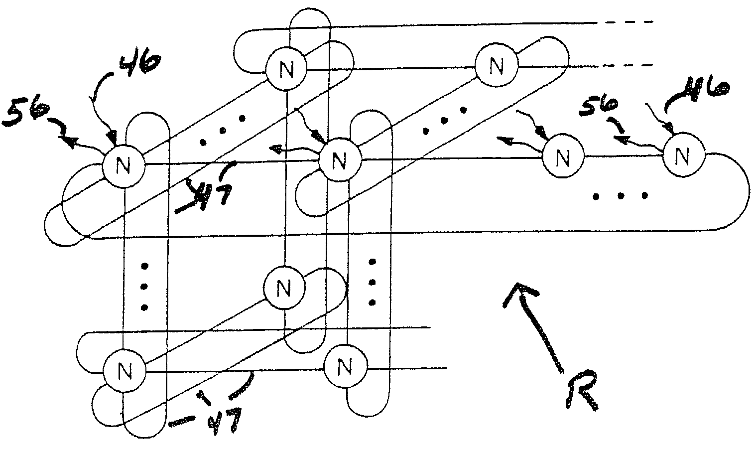
[0032]In implementing an internet router, the present invention borrows from multiprocessor technology and modifies that technology to meet the unique characteristics and requirements of internet routers. In particular, each internet router is itself configured as either a direct or indirect network.

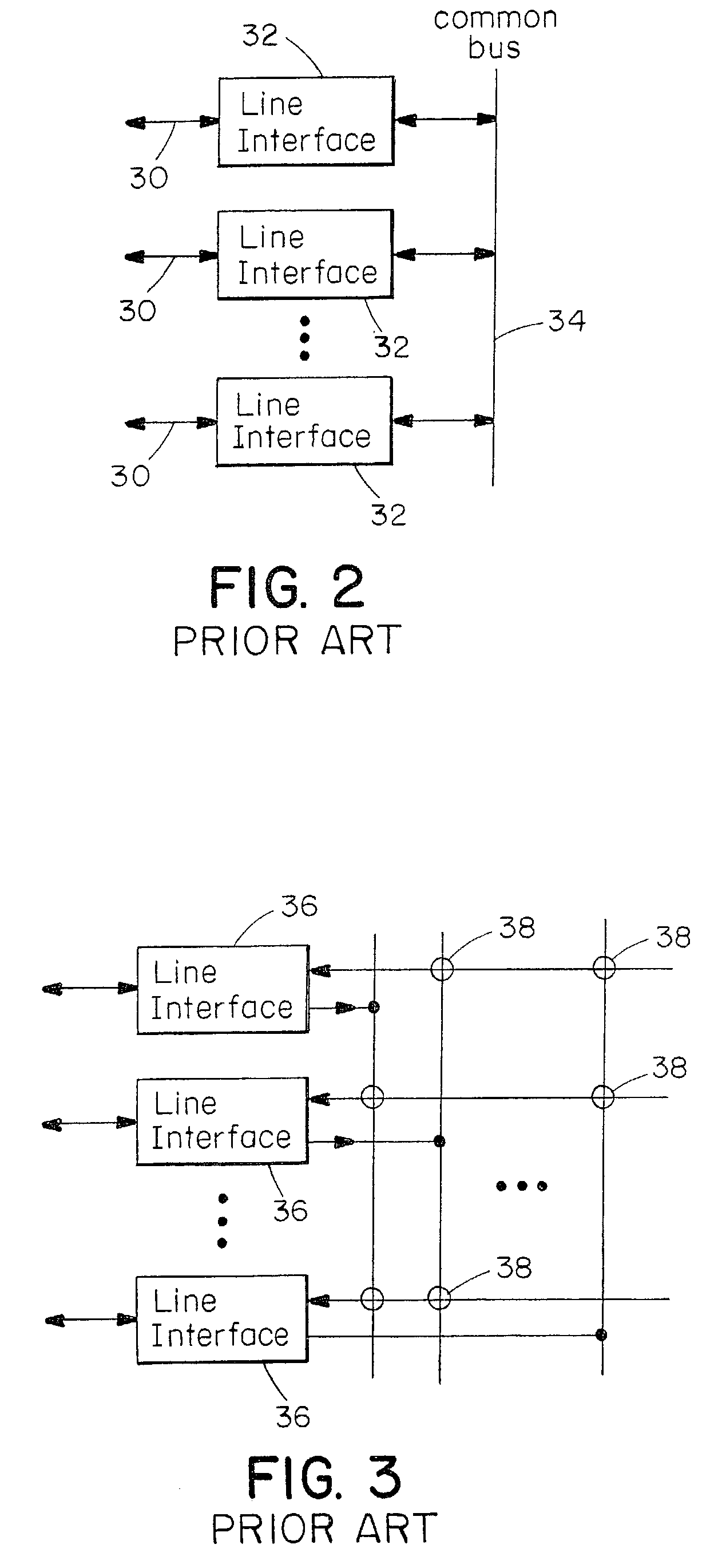
[0033]Multicomputers and multiprocessors have for many years used direct and indirect interconnection networks to send addresses and data for memory accesses between processors and memory banks or to send messages between processors. Early multicomputers were constructed using the bus and crossbar interconnects shown in FIGS. 2 and 3. However, to permit these machines to scale to larger numbers of processors they switched to the use of direct and indirect interconnection networks.

[0034]A direct network, as illustrated in FIG. 4, is comprised of a set of processing nodes 40, each of which includes a router, R, along with a processor, P, and some memory, M. These multicomputer routers shou...


PUM


Abstract

An internet router is implemented as a network fabric of fabric routers and links. The internet router receives data packets from trunk lines or other internet links and analyzes header information in the data packets to route the data packets to output internet links. The line interface also analyzes the header to define a fabric path through the router fabric. The internet packets are broken into flits which are transferred through the router according to a wormhole routing protocol. Flits are stored in fabric routers at storage locations assigned to virtual channels corresponding to destination internet links. The virtual channels and links within the fabric define virtual networks in which congestion in one virtual network is substantially nonblocking to data flow through other virtual networks. Arbitration is performed at each fabric router to assign packets to virtual channels and to assign virtual channels to output fabric links. A virtual channel is enabled for possible assignment to an output fabric link upon receipt of an indication that an input buffer is available at the next fabric router of the path.

Description

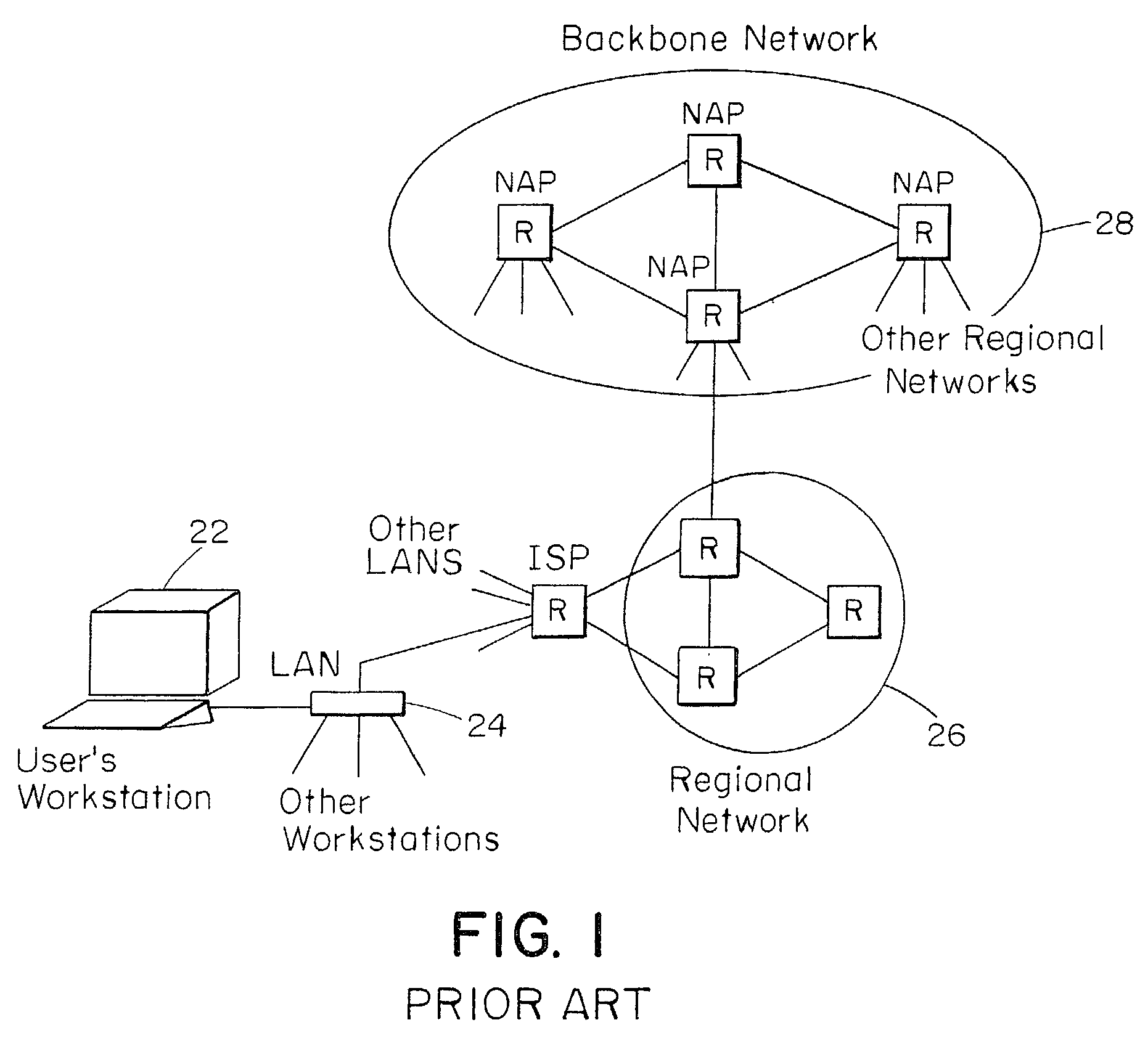
RELATED APPLICATIONS[0001]This application is a continuation of U.S. application Ser. No. 10 / 017,362, filed on Dec. 14, 2001 now abandoned, which is a continuation of U.S. application Ser. No. 08 / 918,556, filed on Aug. 22, 1997 now U.S. Pat. No. 6,370,145. The entire teachings of the above applications are incorporated herein by reference.BACKGROUND OF THE INVENTION[0002]Data communication between computer systems for applications such as web browsing, electronic mail, file transfer, and electronic commerce is often performed using a family of protocols known as IP (internet protocol) or sometimes TCP / IP. As applications that use extensive data communication become more popular, the traffic demands on the backbone IP network are increasing exponentially. It is expected that IP routers with several hundred ports operating with aggregate bandwidth of Terabits per second will be needed over the next few years to sustain growth in backbone demand.[0003]As illustrated in FIG. 1, the Inte...

Claims


Application Information

Patent Timeline
Patent Type & Authority Patents(United States)
IPC IPC(8): H04L12/56H04L29/06
CPCH04L45/06H04L45/10H04L49/10H04L49/251H04L69/168H04L69/16H04L69/166H04L69/161H04L49/30H04L49/101H04L49/50H04L49/505H04L49/112
Inventor DALLY, WILLIAM J.CARVEY, PHILIP P.DENNISON, LARRY R.KING, P. ALLEN
Owner FUTUREWEI TECH INC
Learn More