
Rolling element bearing and motor

a technology of rolling bearing and roller, which is applied in the direction of thickeners, rotary machine parts, mechanical equipment, etc., can solve the problems of abnormal noise generation of bearings, deterioration of the outer ring of bearings which has been prepared with substantially complete roundness, and offensive noise generated by bearings, etc., to achieve low noise and vibration, and maintain the effect of performance for a long tim

Inactive Publication Date: 2007-03-06
NSK LTD
View PDF10 Cites 8 Cited by
  • Summary
  • Abstract
  • Description
  • Claims
  • Application Information

AI Technical Summary

Benefits of technology

The present invention relates to a rolling bearing for supporting a shaft on which a fan is provided. The bearing has inner and outer rings with balls and a retainer, and a space inside the bearing. The bearing is designed to prevent deformation and noise, and to inhibit the generation of abnormal noise from the bearing. The invention also relates to a motor with the shaft supported by the rolling bearing. The residual austenite content in the inner ring is set to be 7 wt % or less to prevent aging deformation. The rolling bearing has a high level of stability and durability.

Problems solved by technology

Further, the fan motor is often used particularly in a situation where noise generated from the bearing is offensive.
Since precision (roundness, cylindricality, etc.) of holes of the press-formed housing, in which the outer ring of the bearing is fitted, is not so high, the precision of the outer ring of the bearing which has been prepared with substantially complete roundness can be deteriorated by the housing, causing the generation of abnormal noise from the bearing in this case.
Accordingly, fitting between the shaft and the inner ring is changed into clearance fit and generates vibration and noise.

Method used


Image

  • Rolling element bearing and motor
  • Rolling element bearing and motor
  • Rolling element bearing and motor

Examples


first embodiment

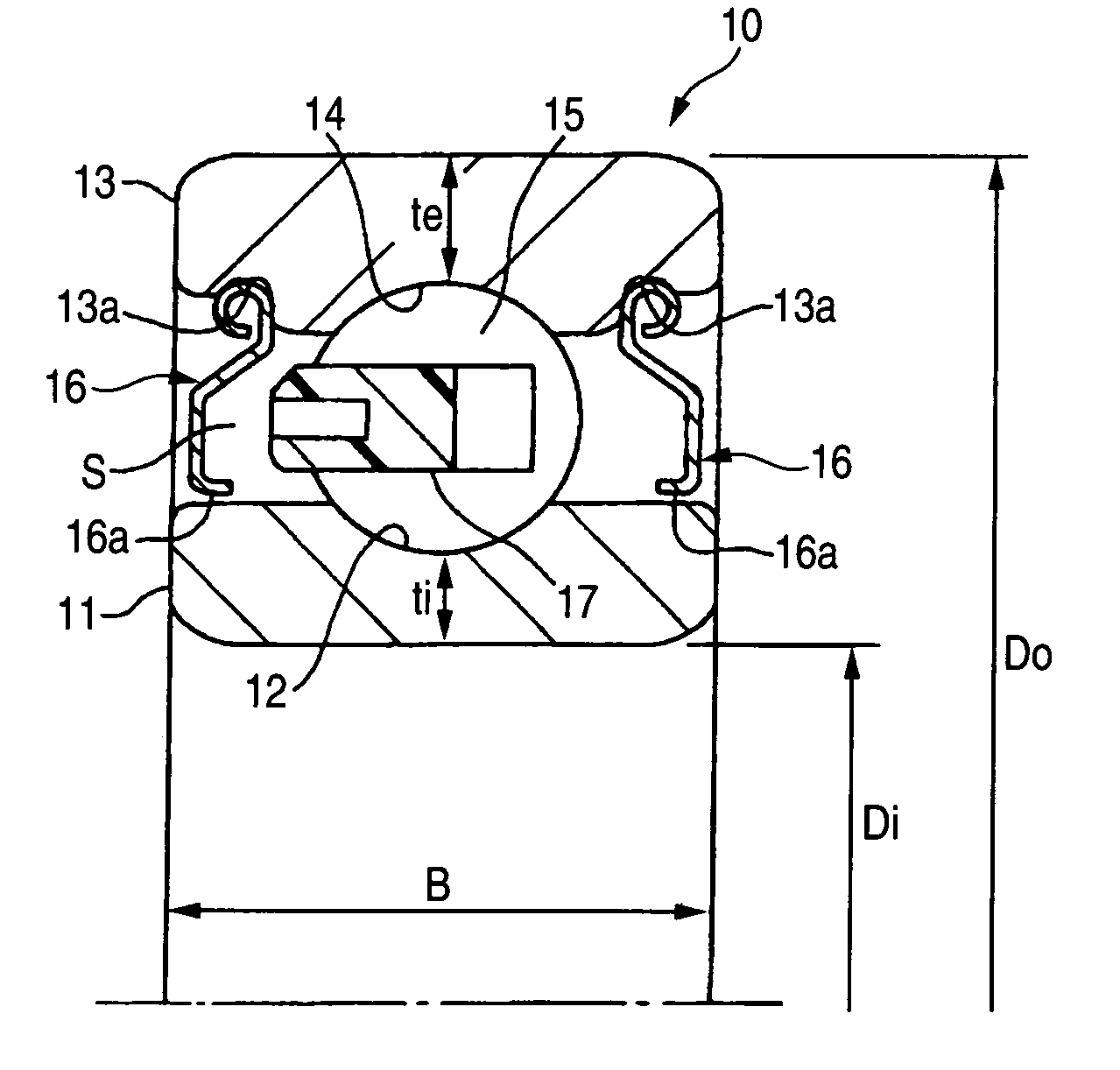
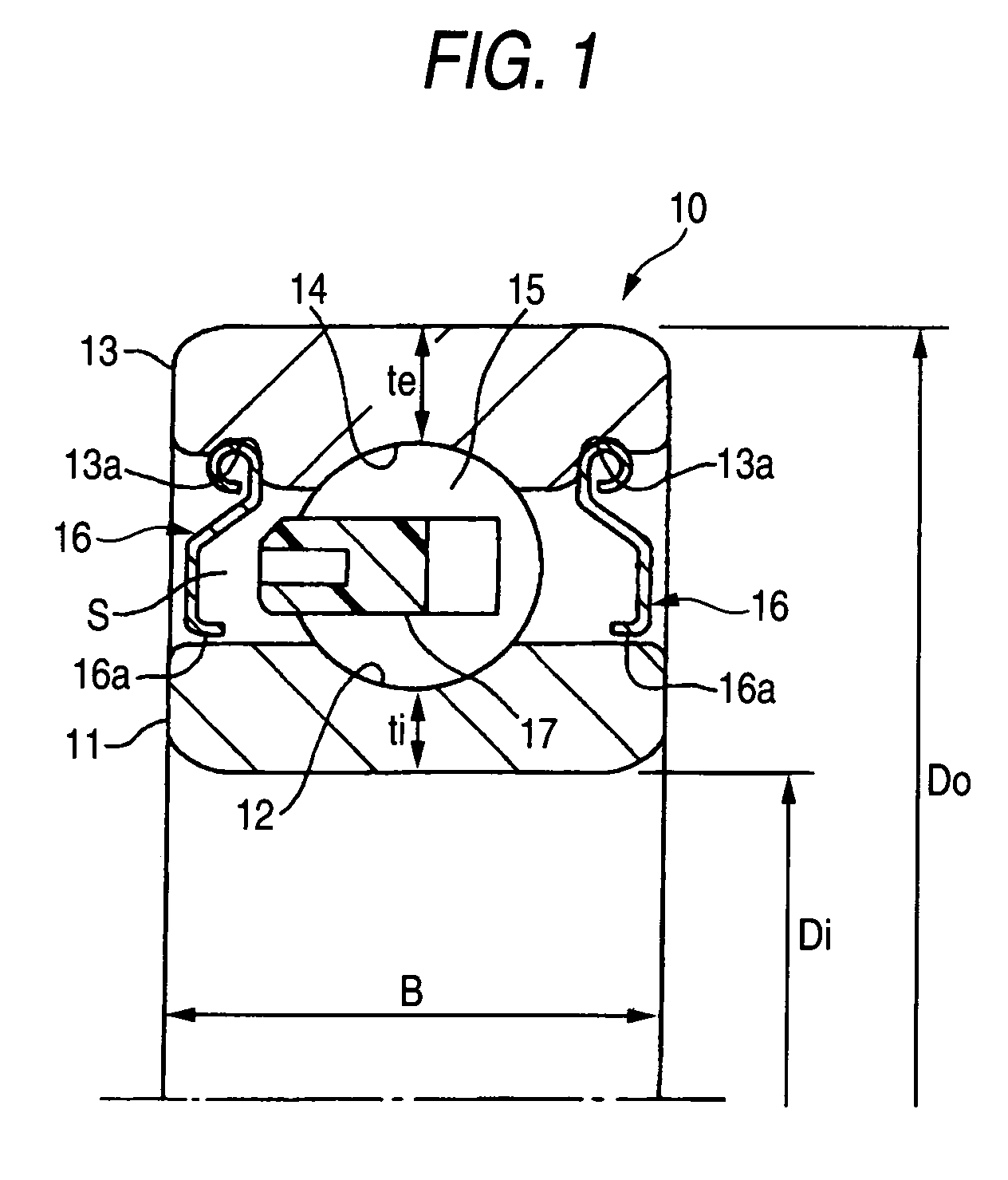
[0024]FIG. 1 is a sectional diagram illustrating a rolling bearing according to the present invention;

second embodiment

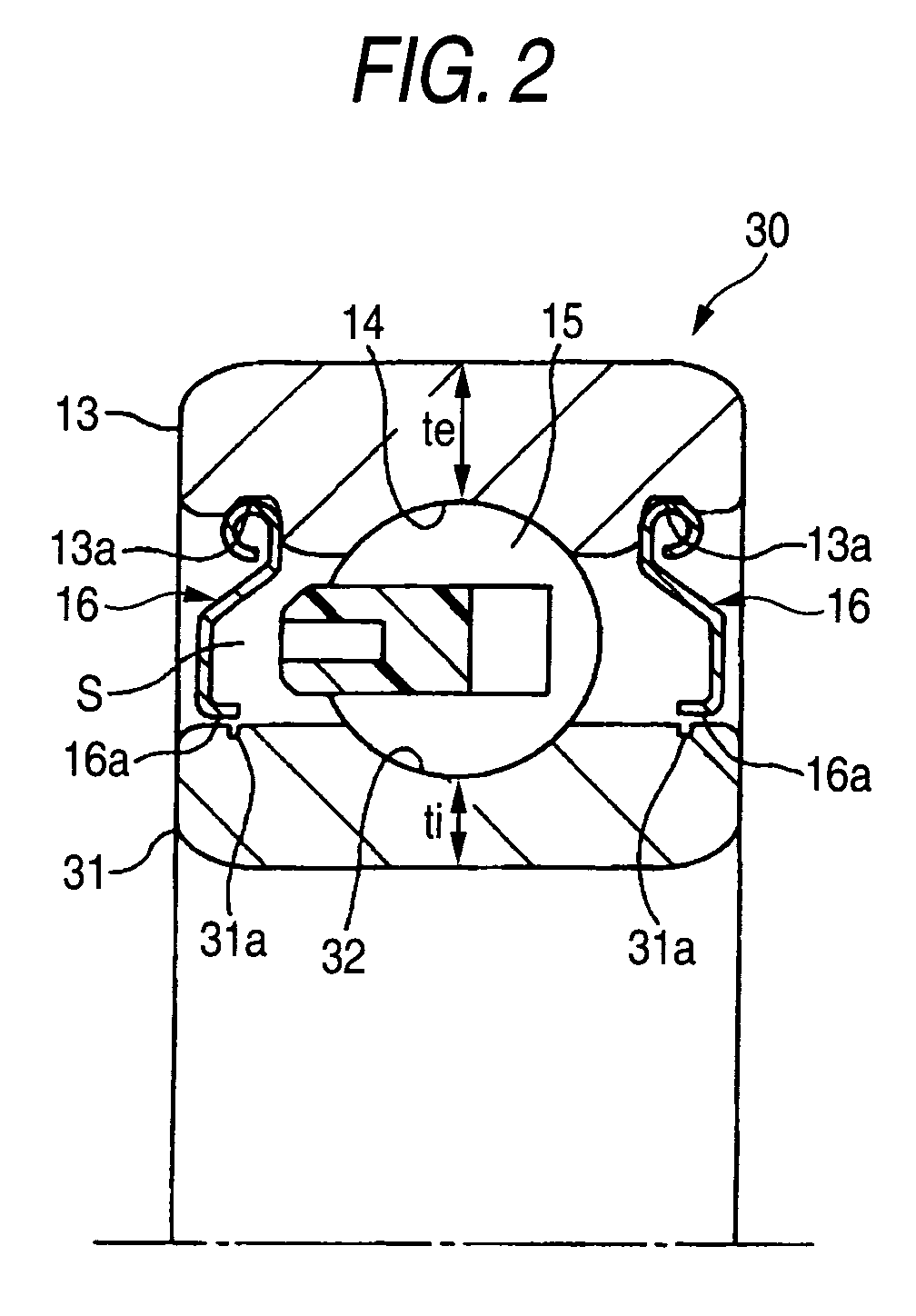
[0025]FIG. 2 is a sectional diagram illustrating a rolling bearing according to the present invention;

third embodiment

[0026]FIG. 3 is a sectional diagram illustrating a rolling bearing according to the present invention;

[0027]FIG. 4 is a sectional diagram illustrating a motor to which the rolling bearing according to the present invention is applied;

[0028]FIG. 5 is a graph illustrating the relationship between the decomposition of residual austenite and the dimensional change ratio; and

[0029]FIGS. 6A and 6B are sectional diagrams illustrating a related art rolling bearing.


PUM

PropertyMeasurementUnit
inner diameteraaaaaaaaaa
outer diameteraaaaaaaaaa

Abstract

A rolling bearing for supporting a shaft on which a fan is provided, has an inner ring having an inner ring race on an outer surface thereof, an outer ring having an outer ring race on an inner surface thereof, balls provided between the inner ring race and the outer ring race and a retainer which keeps the balls apart each other in a circumferential direction, wherein an inner diameter of the bearing is set to be 3 mm or more and 17 mm or less, an outer diameter of the bearing is set to be 8 mm or more and 40 mm or less, when a thickness ti and a thickness te satisfies a relationship te≧1.24 ti, and a residual austenite content in the inner ring is 7 wt % or less.

Description

FIELD OF THE INVENTION[0001]The present invention relates to a rolling bearing which is preferably used to bear the rotor of a motor such as air conditioner fan motor, air purifier fan motor, cleaner (electric cleaner) motor, car air conditioner fan motor, IC cooling fan motor and kotatsu (Japanese foot warmer with a quilt over it) fan motor.DESCRIPTION OF THE RELATED ART[0002]A conventional example of a rolling bearing (ball bearing) for use in the above purposes is shown in FIG. 6(A). As shown in the figure, a ball bearing is arranged such that thickness ti and te at a bottom surface of race, which is the thinnest section of inner and outer rings 91 and 93, respectively, are the same taking into account a balance of strength of the inner ring 91 and the outer ring 93.[0003]Japanese Patent Unexamined Publication No. JP-A-2001-90736 proposes that a pitch diameter Dp of ball is sety to be smaller than a sectional center diameter of the bearing as shown in FIG. 6(B) for the purpose of...

Claims


Application Information

Patent Timeline
Patent Type & Authority Patents(United States)
IPC IPC(8): F16C33/58C10M115/08C10M119/24C10M169/00C10M169/06F16C19/06F16C33/62F16C33/64F16C33/66H02K5/173
CPCC10M115/08C10M119/24C10M169/00C10M169/06F16C33/62F16C33/64F16C33/6633H02K5/1732F16C2240/40C10M2215/1026
Inventor TAKEI, KENJITERADA, YASUHISA
Owner NSK LTD
Learn More