
System for the secondary suspension of a superstructure of a rail vehicle having a passive spring element

a superstructure and passive spring technology, applied in the direction of passenger carriages, carriages, and resilient suspensions, can solve the problems of lowering the superstructure, the superstructure level may change, and the emergency level n/sub>cannot be guaranteed under all conditions

Active Publication Date: 2007-03-06
KNORR BREMSE SYST FUR SCHIENENFAHRZEUGE GMBH
View PDF40 Cites 21 Cited by
  • Summary
  • Abstract
  • Description
  • Claims
  • Application Information

AI Technical Summary

Benefits of technology

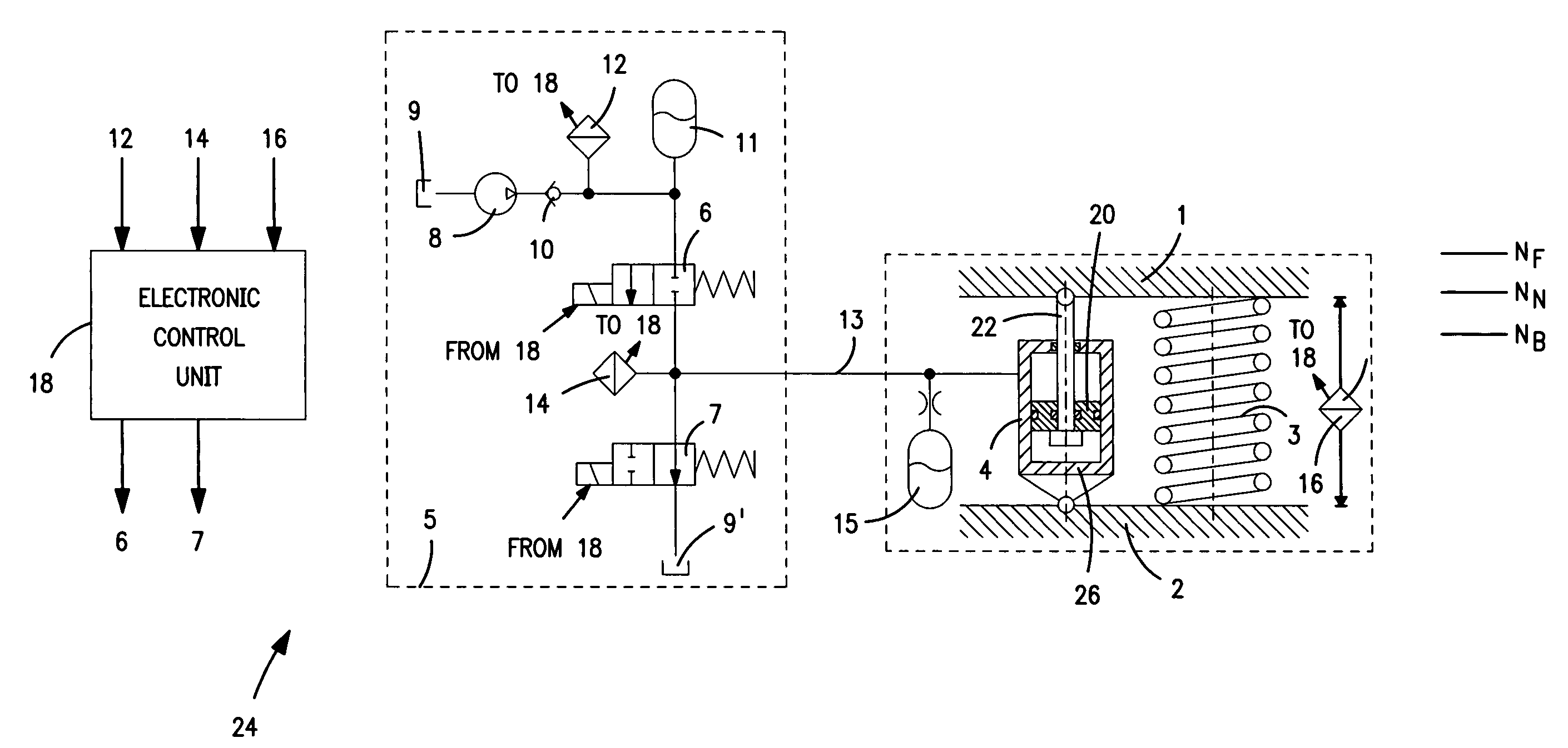
[0006]In certain application cases, it is defined that, in addition to a raised traveling level NF, the superstructure also has to take up a station platform level NB which is below it and which, in a lowered position of the superstructure matches the door steps of the rail vehicles with the height of the station platform, so that an entering and exiting becomes possible without steps. Furthermore, safety-related regulations require that, despite such a lowered station platform level NB, in the case of a system failure, the superstructure of the rail vehicle can also independently take up a so-called emergency level NN situated slightly above it. This emergency level NN situated between the lowered station platform level NB and the raised traveling level NF, despite the system failure, permits an at least slow continued traveling of the rail vehicle.
[0008]Furthermore, the known system for the secondary suspension has a fairly high-cost construction, which applies particularly to the construction of the spring leg constructed in the manner of a lifting cylinder.
[0012]According to the present disclosure, in the event of a system failure, the tension cylinder is automatically depressurized so that the parallel steel spring rebounds. During a stoppage, that is, in the area of the station stop, this has the effect that, from the lowered station platform level NB, the superstructure arrives at a higher level, which here corresponds to the traveling level NF, so that a continued traveling of the rail vehicle becomes possible. Also, according to the present disclosure, simple construction elements are employed, such as a conventional steel spring as well as a hydraulic cylinder available as a standardized component.
[0013]The tension cylinder should preferably be arranged locally next to the steel spring while acting between the superstructure and the bogie. This arrangement ensures a good access to the tension cylinder as well as to the steel spring from the outside for servicing or repair. As an alternative, it is also conceivable to arrange the tension cylinder inside the steel spring, constructed as a coil spring, and acting between the superstructure and the bogie. In comparison to the former arrangement, this provides a space-saving housing which should be selected when required by a narrow installation situation.
[0018]In order to prevent a taking-in of hydraulic oil from the tank during a deflection of the steel spring as a result of vibrating movements during the travel, the tension cylinder has a piston which takes along a piston rod originating therefrom only in the moving-in direction, whereas, in the moving-out direction, the piston is uncoupled therefrom. By this simple mechanical uncoupling, a disturbing suction intake is avoided.

Problems solved by technology

However, when a secondary suspension is constructed by steel springs as passive spring elements, the problem arises that the superstructure level may change as a function of the loading.
Without any level control system, this would result in a lowering of the superstructure, as in the case of the above-described passive spring element.
In the case of the known system for the secondary suspension with an active level control, however, an emergency level NN starting from a traveling level NF can only be adjusted if sufficient stored pressure is present in the supply reservoir and the assigned valve is operated manually.
Thus, an emergency level NN cannot be ensured under all conditions.
Furthermore, the known system for the secondary suspension has a fairly high-cost construction, which applies particularly to the construction of the spring leg constructed in the manner of a lifting cylinder.

Method used


Image

  • System for the secondary suspension of a superstructure of a rail vehicle having a passive spring element
  • System for the secondary suspension of a superstructure of a rail vehicle having a passive spring element

Examples


Embodiment Construction

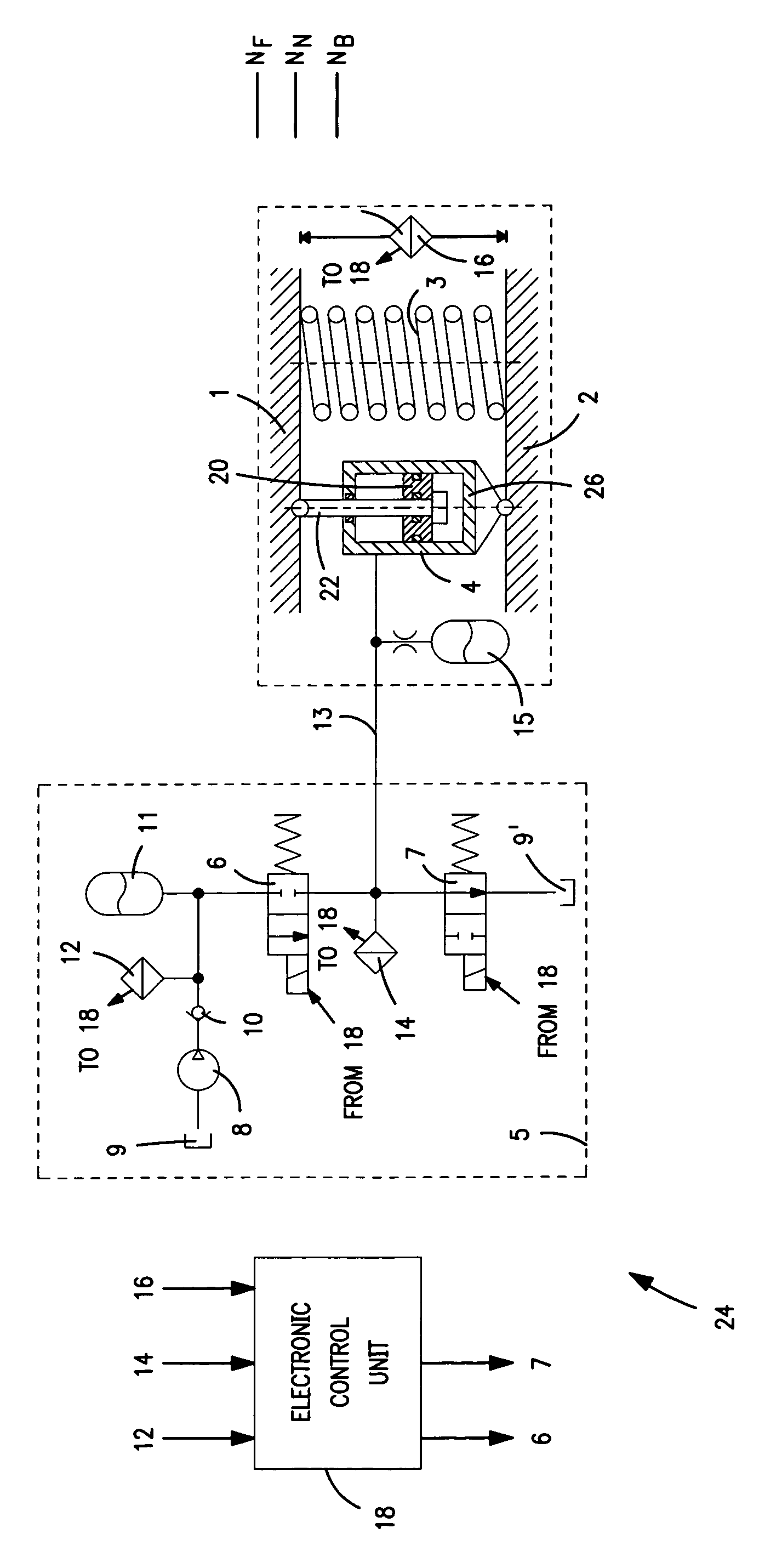
[0022]According to the FIGURE, a steel spring 3 is arranged as a passive spring element, between an upper superstructure 1 of a rail vehicle (not shown in detail) and a lower bogie 2. During travel of the rail vehicle, the steel spring 3 ensures at least one traveling level, shown as a raised traveling level NF for the superstructure 1, so that the superstructure 1 remains unaffected by disturbing vibrations caused by the travel. The steel spring 3 simultaneously takes over the transverse suspension of the superstructure 1. A tension cylinder 4 is connected in parallel to the steel spring 3. To this extent, the tension cylinder 4 also acts between the upper superstructure 1 and the lower bogie 2 and is linked to both. The tension cylinder 4 is used for a compression of the adjacent steel spring 3, so that the superstructure 1 can be changed from its normal traveling level NF to a lowered station platform level NB. At this lower station platform level NB, door steps of entrance doors...


PUM


Abstract

A secondary suspension for a rail vehicle includes a superstructure, a bogie and a steel spring arranged between the superstructure and the bogie. The steel spring ensures at least one raised traveling level for the superstructure when the rail vehicle is traveling. Further included is a tension cylinder. When the rail vehicle is stopped, the steel spring is compressed by the tension cylinder to adjust the superstructure to a lowered station platform level below the at least one traveling level.

Description

BACKGROUND AND SUMMARY[0001]The present disclosure relates to a system for the secondary suspension of a superstructure of a rail vehicle. The system includes a steel spring as a passive spring element arranged between the superstructure and a bogie. The steel spring ensures as least one raised traveling level NF for the superstructure when the rail vehicle is traveling.[0002]A secondary suspension between a superstructure and a railborne bogie of a rail vehicle is used particularly for the additional vibration isolation of the superstructure in order to permit a comfortable travel when conveying passengers. In many cases, the secondary suspension also interacts with a roll control for the superstructure. In addition to the secondary suspension used for the increase of comfort, a rail vehicle of the type of interest here also has a primary suspension. The primary suspension acts between the wheel axles of the rail vehicle and the bogie and is used predominantly for absorbing hard sh...

Claims


Application Information

Patent Timeline
Patent Type & Authority Patents(United States)
IPC IPC(8): B61F1/00B60G17/027B60G17/04B61F5/02B61F5/14
CPCB60G17/0272B61F5/14B61F5/02B60G17/0416
Inventor HOMMEN, WINFRIEDKIRSCH, HENRYLEHMAIR, MARTINLOEBNER, REINHARDWALDSTEIN, MARTINOBERTHUR, RALF
Owner KNORR BREMSE SYST FUR SCHIENENFAHRZEUGE GMBH
Learn More