
Sequential program-verify method with result buffering

a program verification and result technology, applied in the field of nonvolatile memory, can solve the problems of deleterious effect on the performance of the suspension of the sequence program verification procedure, and the overall cost so as to improve the production process of the memory device, reduce the overall cost, and reduce the length of the procedure

Active Publication Date: 2007-02-27
MICRON TECH INC
View PDF8 Cites 9 Cited by
  • Summary
  • Abstract
  • Description
  • Claims
  • Application Information

AI Technical Summary

Benefits of technology

This approach reduces the length of the program-verify procedure, enhances production process performance, and lowers the overall cost of memory device production by avoiding unnecessary interruptions during testing.

Problems solved by technology

A drawback of the solution described above is that the sequential program-verify procedure must be suspended (for outputting the indication of the defecting columns) whenever an error condition is detected.
This drawback has a deleterious effect on the performance of the production process of the memory devices and then on their overall cost.

Method used


Image

  • Sequential program-verify method with result buffering
  • Sequential program-verify method with result buffering
  • Sequential program-verify method with result buffering

Examples


Embodiment Construction

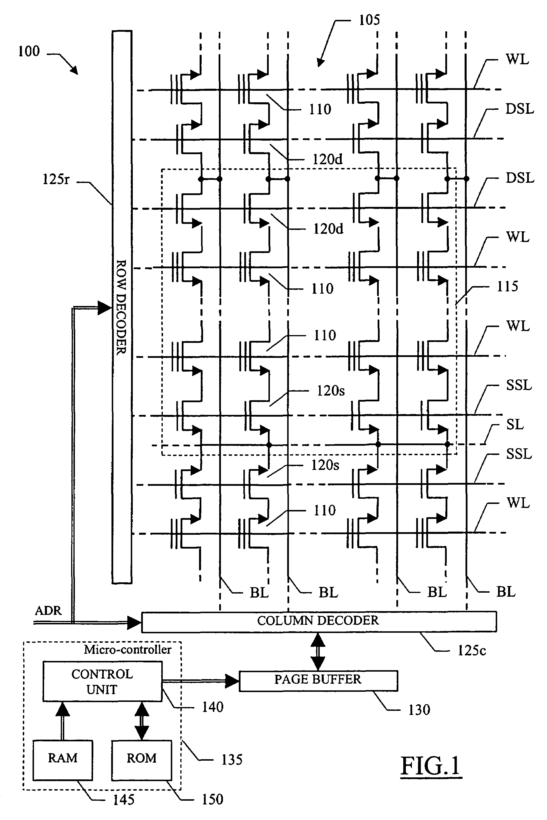
[0015]With reference in particular to FIG. 1, a non-volatile memory device 100 (consisting of an E2PROM of the flash type) is illustrated. The flash memory 100 is integrated in a chip of semiconductor material, and includes a matrix 105 (or more) of memory cells 110; typically, each cell 110 consists of a floating gate NMOS transistor. In an erased condition, the cell 110 has a low threshold value (associated with a logic value 1). The cell 110 is programmed by injecting electric charges into its floating gate; in this condition, the cell 110 has a high threshold value (associated with a logic value 0). Therefore, when a selected cell 110 is biased for reading, the cell 110 will be conductive if erased or non-conductive if programmed.

[0016]The cells 110 are organized into a plurality of rows (for example, 2048) and a plurality of columns (for example, 4096). The flash memory 100 has a so-called NAND architecture. In this configuration, the matrix 105 is partitioned into multiple sec...


PUM


Abstract

A sequential program-verify method is used in a non-volatile memory device including a plurality of memory cells each one for storing a logic value, the cells being arranged into a plurality of alignments. The method includes the steps of: writing a set of target values into a plurality of blocks of cells, the corresponding cells of each block belonging to a common alignment, verifying each block of cells in succession to assert a fault value for each alignment in response to a non-compliance of the value stored in the cell of the block belonging to the alignment with the corresponding target value, buffering the fault values, and in response to the verification of all the blocks of cells providing an indication of the alignments being defective according to the fault values.

Description

BACKGROUND OF THE INVENTION[0001]1. Field of the Invention[0002]The present invention relates to the non-volatile memory field, and more specifically to a sequential program-verify method for use in a non-volatile memory device.[0003]2. Description of the Related Art[0004]Non-volatile memory devices (such as E2PROM of the flash type) are commonly used in several applications when the data stored in the memory device must be preserved even if a power supply is off. Typically, the memory device includes a matrix of memory cells (for example, arranged in rows and columns according to a NAND architecture); the matrix is partitioned into pages, each one consisting of a block of cells (such as 8) that are read or written at the same time.[0005]The production process of the memory devices includes a series of test procedures, which are used to check their operative characteristics. For example, in a sequential program-verify procedure a predefined data pattern is written throughout the who...

Claims


Application Information

Patent Timeline
Patent Type & Authority Patents(United States)
IPC IPC(8): G11C16/34G11C11/34G11C29/00
CPCG11C16/3454
Inventor VORRARO, GIOVANNI FRANCESCOVILLANI, PAOLO
Owner MICRON TECH INC
Learn More